
On a heavy truck or a coach, the road speed you see on the dashboard usually does not come from the ABS sensors or from the engine. In most European trucks it starts at a small sensor screwed into the gearbox housing, passes through the tachograph and is then shared with every control unit that needs it. This article explains how the tachograph motion sensor works, how the signal is calibrated and protected, which ECUs use it, and how to diagnose faults when it goes missing.
What the tachograph does
A tachograph is a recording device fitted to goods vehicles and buses that fall under driving-time rules in the EU and many other countries. It records driving time, rest periods, speed and distance, linked to the driver card that is inserted. Because these records are used for enforcement, the speed and distance data must be trustworthy. That is why the sensor, the vehicle unit and the way they are connected are regulated, sealed and checked at periodic inspections.
Digital tachographs store data in memory and on driver cards, and current “smart” units add a GNSS receiver. For a technician, the key point is that the tachograph is very often the master source of road speed for the whole truck.
How the motion sensor works
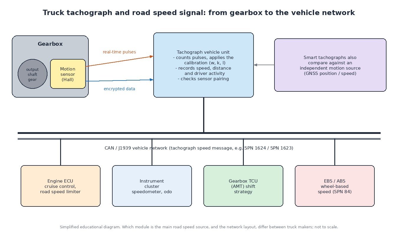
The motion sensor sits in the gearbox, usually near the output shaft, and reads a toothed or slotted target that turns with the shaft. Modern sensors use Hall-effect elements, so they produce a clean square-wave signal even at very low speed. The faster the shaft turns, the higher the pulse frequency.
With a digital tachograph the sensor is more than a pulse generator. It has two channels. One carries the real-time speed pulses. The other is a data link over which the sensor and vehicle unit exchange encrypted information. During installation the sensor is paired with one specific vehicle unit, so the tachograph can tell whether the sensor it is talking to is the genuine paired one and whether the two channels agree. If they do not, the tachograph records a fault or a security event.
Because a speed sensor alone can be fooled, smart tachographs also compare the vehicle motion they calculate from the sensor with an independent source, such as speed and position from GNSS. A large mismatch is logged as a motion conflict.
Calibration: turning pulses into kilometres
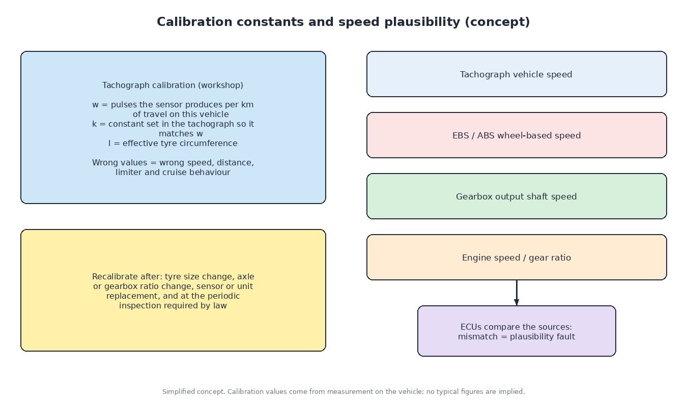
A pulse frequency means nothing until the tachograph knows how many pulses equal one kilometre on that particular truck. That depends on the gearbox output gear, the axle ratio and the rolling size of the drive tyres. An authorised tachograph workshop measures this on the vehicle and programs three key values:
- w – the characteristic coefficient of the vehicle: how many pulses the sensor produces per kilometre travelled.
- k – the constant of the recording equipment, set in the tachograph to match w.
- l – the effective circumference of the drive tyres.
If any of these is wrong, the speed and distance are wrong, and so is everything downstream: the speedometer, the odometer, cruise control and the speed limiter. Recalibration is needed after a tyre size change, an axle or gearbox ratio change, replacement of the sensor or vehicle unit, and at the periodic inspection the law requires (in the EU at least every two years). The workshop also fits a plaque with the calibration data and seals the sensor connection.
Who uses the speed signal
The tachograph broadcasts vehicle speed and output shaft speed on the truck network as J1939 parameters (for example SPN 1624 tachograph vehicle speed and SPN 1623 tachograph output shaft speed). Other units pick it up:
- Engine ECU – cruise control and the road speed limiter, sometimes PTO and idle logic that depends on whether the truck is moving.
- Instrument cluster – speedometer and odometer display.
- Gearbox control unit – an automated manual transmission uses road speed together with its own shaft speed sensors to choose gears.
- Braking system – the EBS calculates its own wheel-based speed (SPN 84) from the wheel speed sensors and shares it on the network.
Having several speed sources is useful. Control units compare tachograph speed, wheel-based speed, gearbox output speed and engine speed divided by the gear ratio. When one source disagrees with the others for too long, a plausibility fault is set. Which source is primary differs between truck makers.
Typical symptoms of a speed signal fault
- Speedometer drops to zero or flickers while driving.
- Cruise control will not engage, or switches off by itself.
- The road speed limiter behaves oddly or the engine enters a reduced mode.
- An AMT shifts late, holds gears or shows a gearbox warning.
- The tachograph shows a sensor fault or records a motion conflict event.
Diagnosis: a practical order
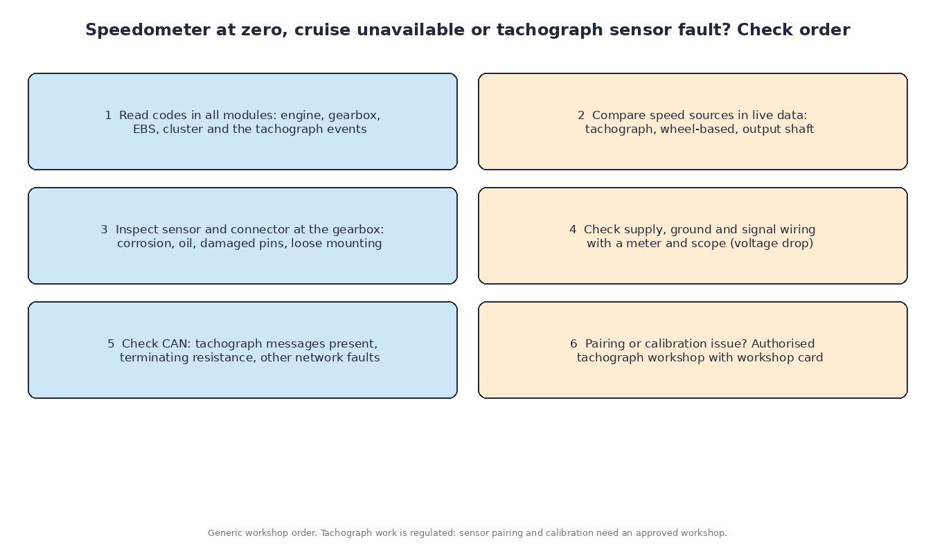
- Read codes from every module, not just the engine: gearbox, EBS, cluster, and the event and fault list stored in the tachograph. The SPN and FMI tell you whether the signal is missing, erratic or simply received in error over the network.
- Compare speed sources in live data during a short drive. If wheel-based speed is fine but tachograph speed is not, look at the motion sensor path. If everything drops at once, think power supply or network.
- Inspect the sensor and connector at the gearbox. Oil ingress, corrosion, pushed-back pins and a loose sensor are common. Respect the seals.
- Check supply, ground and signal wiring. A voltage drop test under load and an oscilloscope on the pulse line show intermittent faults that a meter misses.
- Check the CAN network: are the tachograph messages present, is the termination resistance correct, are other modules logging network faults?
- Pairing and calibration: after a sensor, gearbox or tachograph replacement, the new parts must be paired and calibrated by an authorised workshop with a workshop card. No amount of wiring repair fixes a pairing error.
What this means for ECU tuning
An engine calibration does not change the tachograph, its calibration or its recorded data, and it must not. The road speed limiter on trucks and buses is a legal requirement, and its setting is part of the inspected vehicle data. A professional engine file for a road truck keeps the limiter, cruise logic and speed signal diagnostics exactly as the regulations require. Interfering with the motion sensor or the tachograph is illegal, and modern systems are designed to detect it. Always fix speed-related codes before tuning.
Related fault codes (DTCs)
Heavy trucks mostly report J1939 SPN/FMI codes. Lighter trucks and vans with OBD-style systems may show P-codes instead. The FMI shows the failure type, for example 2 (erratic or incorrect data), 9 (abnormal update rate) or 19 (received network data in error).
| Code | Meaning | Typical causes |
|---|---|---|
| SPN 1624 (+FMI) | Tachograph vehicle speed | Motion sensor or wiring fault, tachograph not sending the message, CAN fault, speed implausible against other sources (FMI 2, 9 or 19 are common) |
| SPN 1623 (+FMI) | Tachograph output shaft speed | Sensor signal lost or erratic, loose sensor in the gearbox housing, damaged connector pins, wrong calibration |
| SPN 84 (+FMI) | Wheel-based vehicle speed | Wheel speed sensor or air gap problem in the ABS/EBS system, missing CAN message, mismatch with tachograph speed |
| SPN 191 (+FMI) | Transmission output shaft speed | Gearbox output speed sensor fault, damaged target wheel, wiring or connector problem |
| SPN 639 (+FMI) | J1939 Network #1 (primary vehicle network) | Open or shorted CAN wires, wrong termination, a module pulling the bus down, water in connectors |
| SPN 168 (+FMI) | Battery potential / power input 1 | Weak batteries, charging fault, poor ground or supply connection causing sensor and module dropouts |
| P0500 | Vehicle speed sensor “A” | No speed signal, sensor or wiring fault, missing network speed message (lighter trucks and vans) |
| P0501 | Vehicle speed sensor “A” range/performance | Signal implausible against engine speed and gear, wrong tyre size or calibration, damaged tone wheel |
| P0502 | Vehicle speed sensor “A” circuit low | Signal wire shorted to ground, open circuit, failed sensor |
| P0503 | Vehicle speed sensor “A” intermittent/erratic/high | Loose connector, chafed wiring, interference on the signal line, sensor fault |
Standard J1939 SPN names and generic SAE J2012 meanings shown. Manufacturer-specific codes, tachograph event codes and which module stores them vary; always check service data.
Planning a tune for your truck, van or car? Upload your original ECU read to ECUFileMarket and get a file prepared for your exact hardware and software version.