
Most new heavy trucks no longer have a clutch pedal, yet underneath they still use a manual gearbox with a dry clutch. The difference is that a transmission control unit (TCU) and a set of pneumatic or electric actuators do the work the driver used to do. This is the automated manual transmission, or AMT. This guide explains how a truck AMT is built, how the TCU shifts together with the engine ECU, and which faults workshops see most.
What an AMT is made of
Dry clutch and clutch actuator
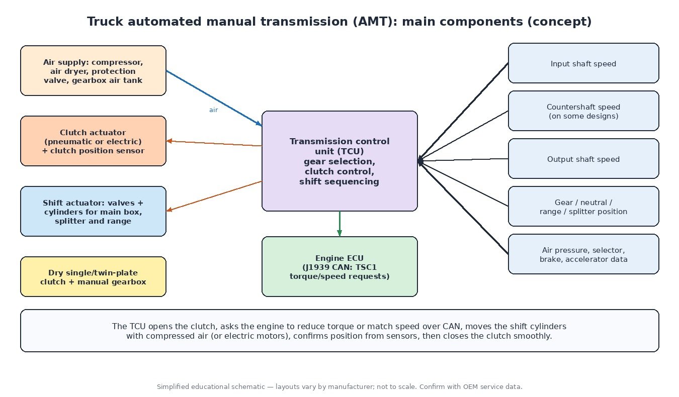
A truck AMT normally keeps a conventional dry single- or twin-plate clutch. Instead of a pedal and hydraulic master cylinder, a clutch actuator opens and closes it. On most heavy trucks this is a pneumatic cylinder fed by the vehicle air system and controlled by fast solenoid valves; some newer and lighter designs use an electric motor. A clutch position sensor tells the TCU exactly where the release bearing is, so it can control slip precisely at take-off and during shifts.
Gear shift actuator
Heavy truck gearboxes typically combine three sections: a main box with a few ratios, a splitter that divides each ratio into a high and low step, and a range section (often a planetary set) that doubles the number of gears. An AMT moves each section with its own actuator, usually electro-pneumatic: solenoid valves send air to cylinders that move the selector rails, while the TCU may also select the shift gate. Electric shift actuators exist as well, especially in smaller gearboxes.
Sensors
The TCU reads input shaft speed, output shaft speed (which also gives road speed), and on many designs countershaft speed. Position sensors report the gear, neutral, splitter and range positions, plus clutch travel. It also uses air pressure, selector lever or buttons, brake and accelerator information, much of it received over the CAN bus.
How the TCU chooses a gear
A good human driver looks at the load, the road ahead and the hill. The TCU does the same with data. It estimates vehicle weight from how quickly the truck accelerates for a given engine torque, and estimates road grade from the difference between expected and actual acceleration. Some systems also use topographic or GPS data for predictive shifting. From these values it decides:
- Which gear to use for the current speed, load and gradient, aiming to keep the engine in an efficient speed band.
- Skip shifts: a lightly loaded truck on flat road can jump two or more gears at a time, while a heavy truck on a climb shifts one step at a time or holds the gear.
- Start gear: a higher starting gear when empty, a lower one when fully loaded or on an incline.
- Special modes: creep or manoeuvre mode for slow, precise movement at docks and building sites; rocking mode, which lets the driver rock the truck forward and back to get out of soft ground; and off-road or economy programmes.
Working with the engine ECU over J1939
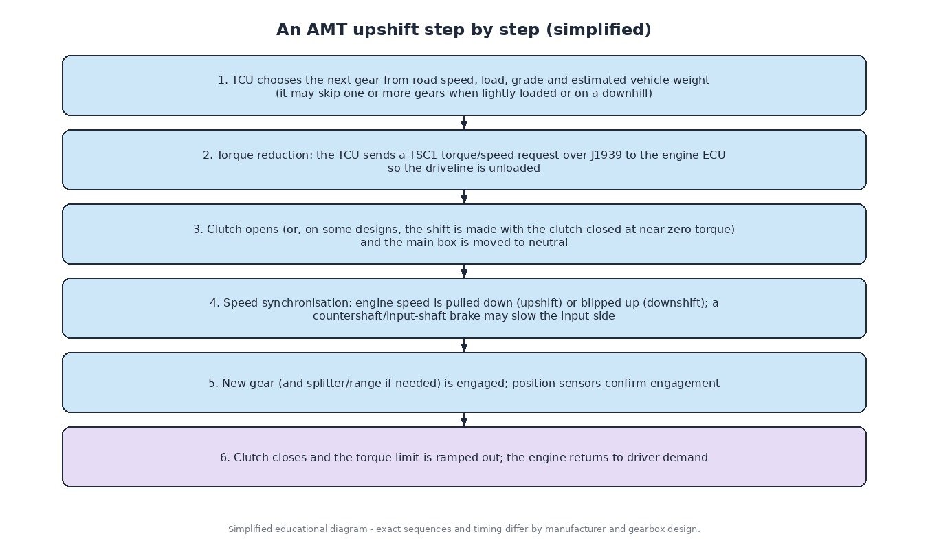
An AMT cannot shift smoothly on its own. It needs the engine to drop torque before the shift and to match speed afterwards. In trucks and agricultural machines this happens over CAN using SAE J1939. The TCU sends the TSC1 (Torque/Speed Control 1) message to the engine ECU, requesting either a torque limit or a target engine speed. During an upshift it asks for reduced torque, the clutch opens or the gear is pulled out at near-zero load, the engine speed falls to the speed needed in the new gear, and the gear engages. On downshifts the engine is asked to raise speed. Many gearboxes also have a countershaft or input-shaft brake to slow the input side faster. Our TCU guide covers transmission control basics in general.
Clutch calibration and learn procedures
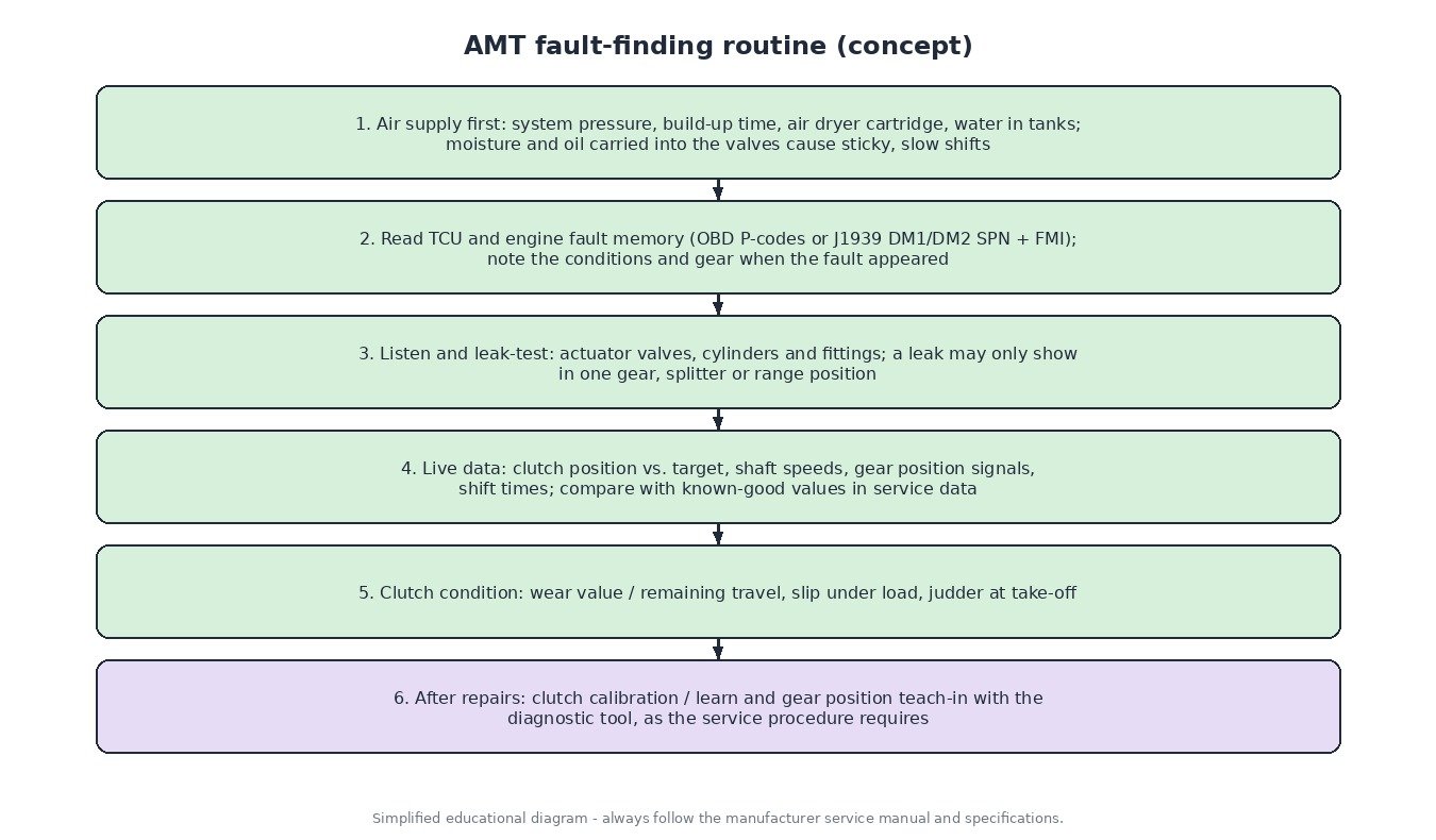
Because the TCU controls clutch slip, it must know the clutch’s real engagement point (often called the kiss or touch point) and the closed and open positions. These values change as the friction plate wears, so the TCU adapts them during operation. After replacing the clutch, the clutch actuator, the position sensor, the gearbox or the TCU, a calibration or learn procedure must be run with a diagnostic tool. Gear position sensors often need a teach-in as well. Skipping this step is a common cause of harsh take-offs, slipping and position fault codes right after a repair.
Common faults
- Air supply and moisture. AMTs depend on clean, dry air at proper pressure. A saturated air dryer cartridge lets water and oil into the valves, which causes sticky actuators, slow shifts and, in winter, frozen valves.
- Air leaks. Leaking cylinders, valve blocks or fittings may only show up in certain gears or splitter/range positions.
- Clutch wear. The TCU tracks remaining clutch travel; a worn clutch gives slip warnings, judder at take-off and eventually a wear fault.
- Sensor faults. Speed sensors with metal debris on the tip, chafed harnesses and corroded connectors produce implausible signals and stop the TCU from shifting.
- CAN and power problems. Low battery voltage, poor grounds or lost communication with the engine ECU can leave the truck stuck in a gear or in neutral.
The same idea in cars and agricultural machines
Single-clutch automated manuals were used in many small cars: a normal manual gearbox with an electro-hydraulic or electric clutch and shift actuator. They are cheap and efficient, but the torque interruption during shifts is more noticeable than in a torque converter or dual-clutch gearbox. Our dual-clutch transmission guide explains how a second clutch removes that interruption. Agricultural tractors more often use powershift or CVT transmissions, but automated shifting of mechanical ranges and electronically controlled clutches follow the same principles of sensors, actuators and J1939 communication with the engine.
Related fault codes (DTCs)
Generic OBD-II/EOBD codes (SAE J2012) that may be used for automated manual transmissions, mainly on cars and light commercial vehicles. Heavy trucks usually report J1939 SPN/FMI codes, explained below the table.
| Code | Meaning | Typical causes |
|---|---|---|
| P0700 | Transmission Control System (MIL Request) | The TCU has stored its own fault and asks the engine ECU to light the MIL; read the TCU memory for the actual code |
| P0705 | Transmission Range Sensor “A” Circuit (PRNDL Input) | Gear selector / range input wiring or connector fault, failed selector switch |
| P0715 | Input/Turbine Speed Sensor “A” Circuit | Input shaft speed sensor, wiring or connector damage, metal debris on the sensor tip, wrong air gap |
| P0720 | Output Speed Sensor Circuit | Output shaft speed sensor or wiring fault, damaged tone wheel, corrosion at the connector |
| P0730 | Incorrect Gear Ratio | Clutch slipping, gear not fully engaged, shift actuator leak or sticking, speed sensor signal errors |
| P0791 | Intermediate Shaft Speed Sensor “A” Circuit | Countershaft (intermediate shaft) speed sensor or wiring fault |
| P0805 | Clutch Position Sensor Circuit | Clutch position sensor wiring, connector or supply fault |
| P0806 | Clutch Position Sensor Circuit Range/Performance | Sensor signal implausible, worn or loose sensor mounting, clutch not calibrated after replacement |
| P0807 | Clutch Position Sensor Circuit Low | Signal shorted to ground, open supply, failed sensor |
| P0808 | Clutch Position Sensor Circuit High | Signal shorted to voltage, open sensor ground, failed sensor |
| P0809 | Clutch Position Sensor Circuit Intermittent | Chafed harness, loose connector, vibration-related contact faults |
| P0810 | Clutch Position Control Error | Clutch does not reach target position: low air pressure, leaking or sticking actuator, worn clutch, missing clutch learn |
| P0900 | Clutch Actuator Circuit/Open | Open actuator valve/motor circuit, connector or wiring fault |
| P0901 | Clutch Actuator Circuit Range/Performance | Actuator response implausible, mechanical binding, internal leakage |
| P0902 | Clutch Actuator Circuit Low | Circuit shorted to ground, failed actuator coil or motor |
| P0903 | Clutch Actuator Circuit High | Circuit shorted to voltage, TCU driver fault |
| P0562 | System Voltage Low | Weak batteries, charging fault, poor grounds; low voltage can slow actuators and reset the TCU |
| U0100 | Lost Communication With ECM/PCM “A” | CAN wiring, terminating resistors, engine ECU power/ground; the TCU cannot request torque reduction |
| U0101 | Lost Communication With TCM | TCU power, ground or fuse, CAN wiring or connector fault, TCU failure |
J1939 trucks and agricultural machines usually report faults as an SPN (Suspect Parameter Number, which signal or component) plus an FMI (Failure Mode Identifier, how it failed). Examples of standard SPNs: 161 Transmission Input Shaft Speed, 191 Transmission Output Shaft Speed, 523 Transmission Current Gear. Common FMIs: 2 = data erratic or intermittent, 3 = voltage above normal or shorted high, 4 = voltage below normal or shorted low, 5 = current below normal or open circuit, 7 = mechanical system not responding or out of adjustment. Active faults are read with DM1 and stored faults with DM2. Manufacturer-specific fault numbers must be checked in the OEM service information.
Summary
An AMT is a manual gearbox with an automated driver: actuators move the clutch and gears, sensors confirm every movement, and the TCU coordinates the shift with the engine through J1939 torque and speed requests. Check air, codes, leaks and live data first, and finish every repair with the correct calibration.
Need a custom-made file for a truck, tractor or car ECU, built from your original read? Send your file to the ECUFileMarket file service.