
Many “faulty ECU” or “bad sensor” diagnoses turn out to be wiring: a corroded ground, a loose terminal, a fuse holder that heats up under load. The fastest way to find them is the voltage drop test, which works on cars, 24 V trucks, tractors and motorcycles alike.
Why an ohmmeter misses high-resistance faults
An ohmmeter pushes a tiny test current through a wire with the circuit switched off. A cable with only a few intact strands, or a terminal with a thin layer of corrosion, can still read close to zero ohms with that small current. Once the circuit carries real current (a fuel pump, a fan, an ECU with all its outputs active) that same resistance drops voltage and creates heat. The component then receives less voltage than it needs.
A voltage drop test measures the circuit while it works, under its normal load.
How to do a voltage drop test
Set a digital multimeter to DC volts and connect it across the section you want to test, not from a point to ground. The meter then shows only the voltage lost in that section.
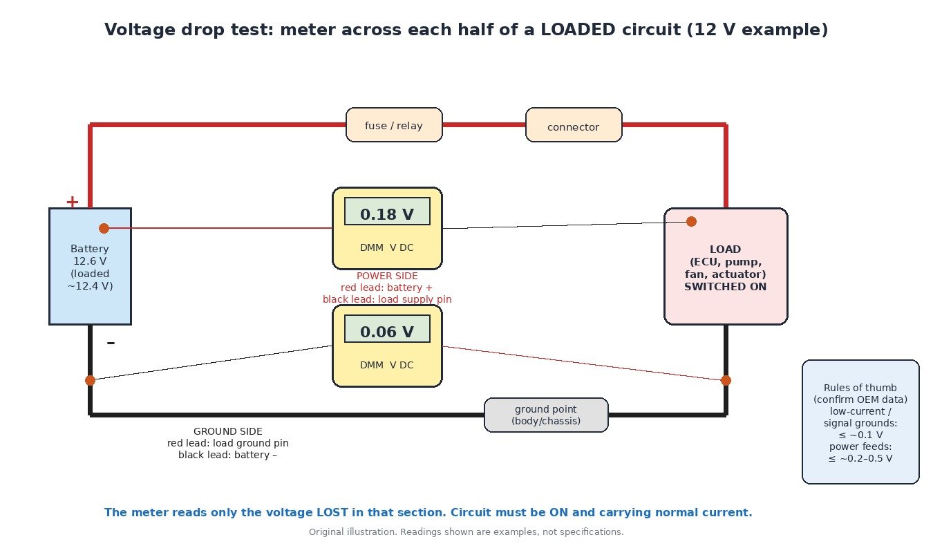
Power side
Red lead on the battery positive post (on the post itself, not the clamp), black lead on the supply pin at the component. Switch the circuit on and operate the load.
Ground side
Red lead on the component’s ground pin or case, black lead on the battery negative post. Operate the load again.
Rules of thumb
Exact limits come from the vehicle manufacturer, but commonly used general guidelines are:
- Electronic and sensor ground circuits: around 0.1 V or less.
- Power feeds to ECUs, pumps and motors: typically a few tenths of a volt; many technicians treat anything much over 0.5 V on a 12 V feed as suspect.
If the total is too high, move one probe step by step towards the other (connector, fuse, ground point) until the drop disappears. The last section you passed contains the fault.
Sensor 5 V reference and signal ground checks
Most pressure, position and pedal sensors use three wires: a 5 V reference from the ECU, a signal, and a dedicated sensor ground returning to the ECU.
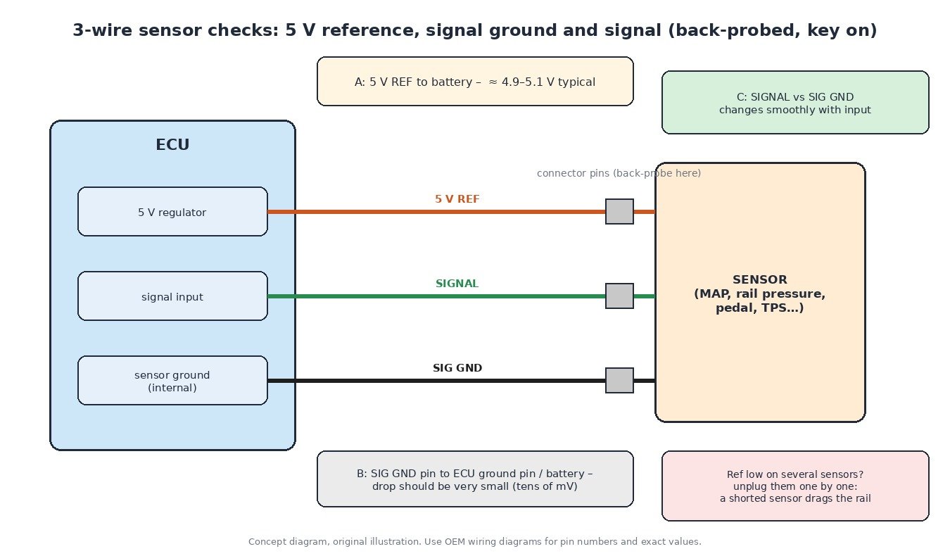
- Reference: key on, back-probe the reference pin to battery negative. It should be close to 5 V. If several sensors share a low reference, unplug them one at a time; a shorted sensor or chafed wire can pull the whole rail down.
- Signal ground: measure from the sensor ground pin to the ECU ground (or battery negative). Even a few hundred millivolts here shifts the signal and can cause plausibility faults or wrong readings, because the ECU reads the signal relative to its own ground.
- Signal: measure signal to sensor ground and check it changes smoothly with pressure, position or temperature.
Back-probing vs piercing
Back-probe connectors from the wire side with thin probes, so the terminal stays connected and the circuit stays loaded. Do not force large probes into the front of female terminals; this spreads them and creates the loose-pin fault you were looking for. Piercing insulation lets water in, causing corrosion along the copper later; if you must pierce, seal the hole afterwards.
Corrosion, pin fit and ground straps
Look for green or white deposits, burnt or discoloured terminals, and pins that slide in with no resistance. Repair with the correct terminals and crimp tool; do not just bend contacts.
ECU and engine ground straps corrode or break as engines move on their mounts. A poor engine ground forces current to find another path (through sensor grounds, throttle cables or shielding), which can cause strange, intermittent faults on several systems at once.
Starter and charging circuits
Voltage drop testing is ideal for slow cranking. Disable starting (fuel or ignition) and measure across the positive cable (battery post to starter terminal) and the ground path (starter body to battery negative) while cranking. Large drops point to cables, terminals or the starter solenoid contacts rather than the starter itself. For how charging is controlled by the ECU, see our guide on smart charging systems, and for battery sensors on start-stop vehicles, see start-stop and IBS.
24 V truck and machine specifics
Most heavy trucks, buses and many large tractors use 24 V from two 12 V batteries in series. A drop that looks small in volts is still lost power, and starter currents are high, so heavy cables, battery isolator switches and chassis ground points need regular checks. Test each battery separately and check the link cable between them. Electronics and sensor grounds still need very low drops, regardless of system voltage. Use OEM data for limits on each circuit.
Low voltage during flashing: how ECUs get bricked
Reading and writing an ECU can take from a few minutes to much longer. With the ignition on, the ECU and other modules, fans and pumps draw current, and battery voltage slowly falls. If the voltage drops too low during a write, the ECU or the interface can reset, the write is interrupted and the ECU may no longer boot.
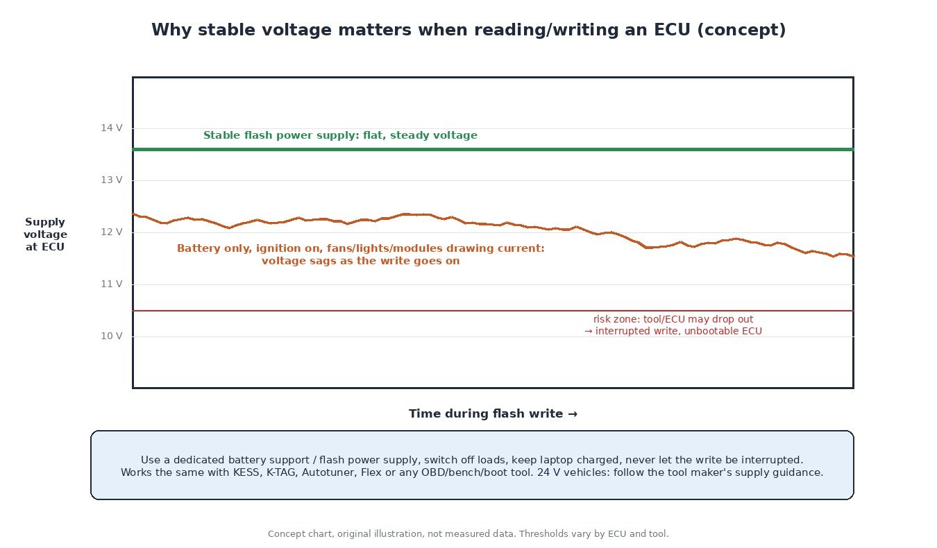
Always connect a dedicated, stable battery support / flash power supply when reading or writing over OBD with tools like KESS, K-TAG, Autotuner or Flex, switch off unnecessary loads, and keep the laptop on mains power. On the bench, use a regulated supply with good, short ground leads, set to the voltage the tool maker recommends for that ECU. Also remember that modified files need valid checksums before writing; on ECUFileMarket, checksum correction is a separate paid option, not included automatically. More on connection methods in our guide to OBD, bench and boot reading.
Step-by-step procedure
- Read all DTCs and freeze frame data in every module; note voltage-related codes and lost-communication codes.
- Check battery condition and resting voltage, then charging voltage with the engine running.
- Switch the circuit on and load it (component working, engine running or cranking if relevant).
- Measure voltage drop on the power side, then on the ground side.
- If a side is too high, move a probe point by point to find the faulty section.
- For sensors, check 5 V reference, signal ground drop and signal behaviour.
- Repair (clean, re-terminate, replace straps or cables), then re-test under load and clear codes. For network faults, see our CAN bus guide.
Related fault codes (DTCs)
| Code | Meaning | Typical causes |
|---|---|---|
| P0560 | System Voltage Malfunction | Poor ECU power feed or ground, corroded battery terminals, charging system fault |
| P0562 | System Voltage Low | Weak battery, voltage drop on the ECU supply or ground, alternator undercharging, high-resistance main fuse/relay |
| P0563 | System Voltage High | Faulty alternator regulator, poor regulator sensing circuit, incorrect jump-start or charger use |
| P0641 | Sensor Reference Voltage “A” Circuit/Open | Open or shorted 5 V reference wire, a shorted sensor pulling the rail down, connector damage |
| P0642 | Sensor Reference Voltage “A” Circuit Low | 5 V reference shorted to ground, chafed harness, internally shorted sensor |
| P0643 | Sensor Reference Voltage “A” Circuit High | 5 V reference shorted to battery voltage, water in connectors |
| P0651 | Sensor Reference Voltage “B” Circuit/Open | As P0641, on the second reference circuit |
| P0697 | Sensor Reference Voltage “C” Circuit/Open | As P0641, on the third reference circuit |
| P0601 | Internal Control Module Memory Check Sum Error | Corrupted or interrupted flash write, incorrect file checksum, internal ECU fault |
| P0606 | Control Module Processor Fault | Internal ECU fault, but check power and ground supply quality first |
| U0100 | Lost Communication With ECM/PCM “A” | ECU not powered or grounded, CAN wiring fault, blown ECU fuse, ECU not booting after a failed flash |
On trucks and agricultural machines using J1939, supply problems often show as SPN 168 (battery potential / power input 1) with an FMI for voltage below or above normal. Code meanings and descriptions can vary slightly by manufacturer; always confirm with OEM documentation.
Summary
Resistance checks do not show how a circuit behaves under load; voltage drop tests do. Measure across the power and ground sides with the circuit working, check sensor references and grounds, protect connectors when probing and always use a stable power supply when flashing.
Need a professional calibration file for your car, truck, tractor or bike? Upload your original read to the ECUFileMarket file service and get a tested file from our tuning team.