
Diesel engines do not need a throttle to control power. Torque comes from the amount of fuel injected, and the engine normally breathes as much air as the turbo can supply. Yet almost every modern diesel in cars, vans, trucks and many off-road machines has an electronic intake throttle valve between the charge-air cooler and the intake manifold. This article explains why it is there, how the ECU controls it, what goes wrong and how to diagnose it.
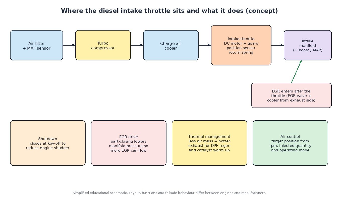
Why a diesel needs an intake throttle
The intake throttle is not a power control. It is an air management tool the ECU uses in specific situations:
- Smooth shutdown: at key-off the valve closes so the engine stops quickly with less shudder. Many vehicles run a short check of the valve at the same time.
- Driving EGR flow: exhaust gas only flows back into the intake if exhaust pressure is higher than intake pressure. At light load that difference can be small, so the ECU partly closes the throttle to lower manifold pressure and pull in the EGR rate it wants. See how EGR works for the full system.
- Exhaust thermal management: reducing the air mass raises exhaust temperature. The ECU uses this during DPF regeneration and catalyst warm-up, together with injection changes. The DPF article covers the regeneration side.
- Air control in special modes: some strategies use the valve during cold running, at idle or when the turbo or EGR system is in a fault reaction.
Under normal driving at medium and high load, the valve is usually fully or nearly fully open.
Construction
A typical unit is a cast housing with a butterfly plate on a shaft, driven by a small DC motor through a reduction gear train. A return spring sets the default position when the motor is not powered. On many designs that default is open or close to open, so the engine can still breathe if the actuator fails, but this depends on the design.
A position sensor reports the plate angle. Older units use a potentiometer track; newer ones use a contactless Hall sensor. Many have two signals so the ECU can check one against the other. The sensor normally gets a 5 V reference and ground from the ECU and returns a voltage that rises or falls with opening.
On some engines the throttle is combined with the EGR mixing point or the EGR valve in one module. The basic principle is the same as the electronic throttle on petrol engines, but the job is different.
How the ECU controls it
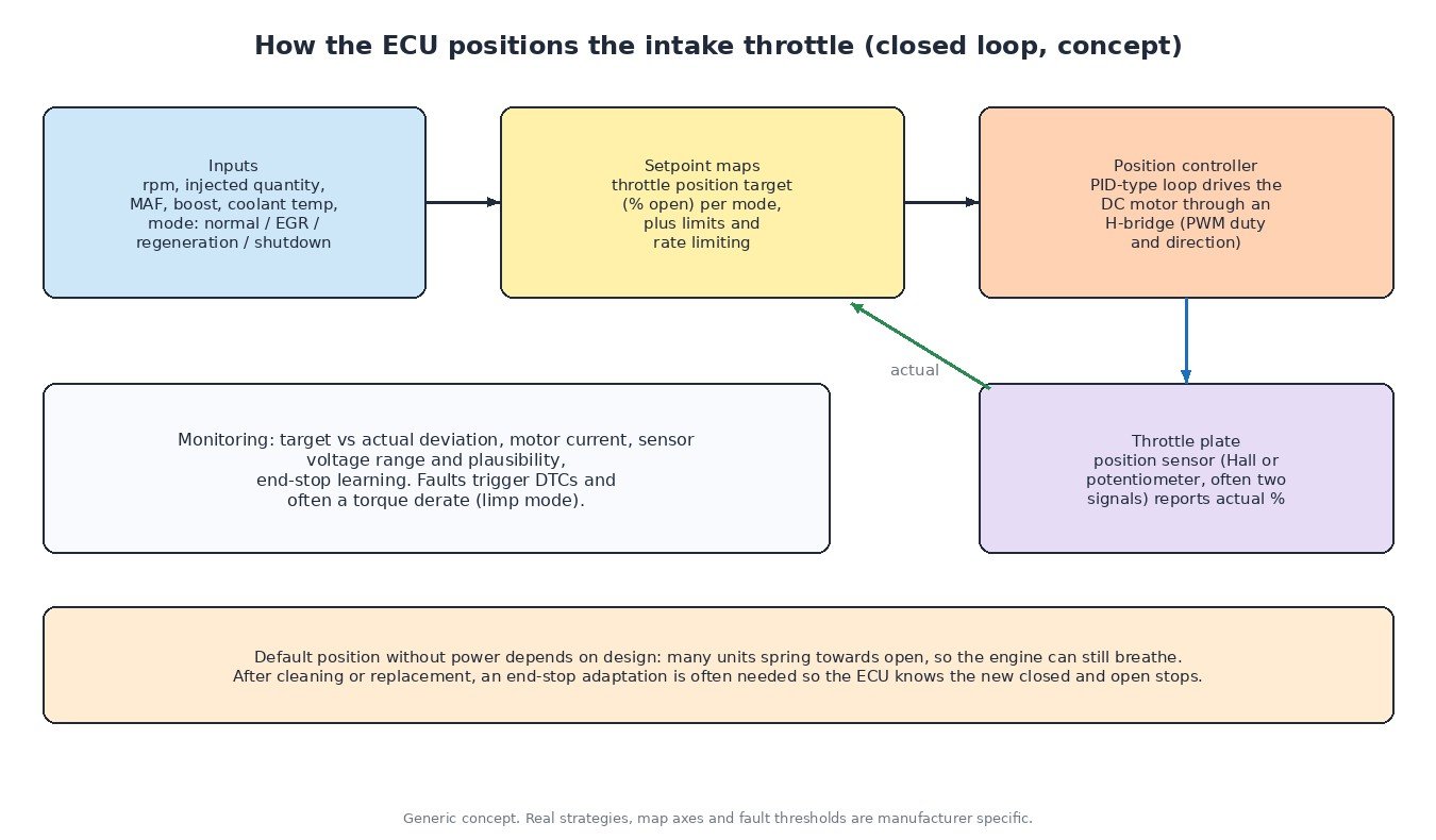
The ECU calculates a target position from maps that depend on engine speed, injected quantity and the active operating mode (normal, EGR, regeneration, warm-up, shutdown). Coolant temperature, boost and air mass from the MAF sensor are typical correction inputs.
A closed-loop position controller then drives the motor through an H-bridge output stage. PWM duty sets the force and the bridge sets the direction, so the ECU can actively open and close the plate. It compares actual with target position all the time.
The ECU also learns the mechanical end stops, often during key-off. If a new or cleaned unit is fitted without this adaptation, the ECU may not position it correctly and can set performance codes.
Monitoring and fault reactions
Typical checks include sensor voltage range, agreement between two position signals, deviation between target and actual position, motor circuit faults and motor current. Many engines also check the result indirectly: if measured air mass does not match what the throttle position should give, the ECU can set high or low airflow codes. Fault reactions often include a warning lamp and reduced torque.
Common failures and symptoms
- Carbon build-up: EGR soot mixed with oil mist from crankcase ventilation forms sticky deposits around the plate and bore. The plate moves slowly or jams.
- Wiring and connector faults: corrosion, chafed harness, broken reference or ground wires.
- Worn gears or motor: the actuator overshoots, chatters or cannot hold position.
- Sensor faults: worn tracks or intermittent signal drop-outs.
Symptoms include the engine warning lamp, limp mode, low power, black smoke or underboost codes when the plate is stuck partly closed, EGR flow codes, regenerations that do not complete, and a harsh shudder at shutdown when the valve no longer closes.
Diagnosis step by step
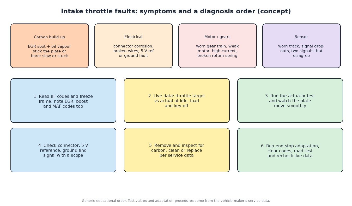
- Read all codes and freeze frame data. Note EGR, boost and MAF codes as well, because they often come from the same root cause.
- Compare target and actual position in live data at idle, under load and at key-off.
- Run the actuator test if your tool offers it and watch the plate move. It should move smoothly without hesitation.
- Check the circuit: connector condition, 5 V reference, ground and signal. A scope shows drop-outs a multimeter misses (see voltage drop testing).
- Remove and inspect for carbon. Clean or replace as the service data recommends, and look for the source of heavy deposits (EGR, crankcase ventilation, oil consumption).
- Run the end-stop adaptation, clear codes, road test and recheck live data.
Why it matters for calibration work
The intake throttle maps sit next to the EGR, air mass and regeneration functions in the ECU. Changing fuelling or boost does not remove the need for this valve: it is still needed for shutdown, EGR operation and exhaust heating. A good calibration keeps its functions and diagnostics working. If an engine shows throttle codes before tuning, fix the hardware first, or the new calibration will be blamed for an old fault.
Related fault codes (DTCs)
Generic OBD-II codes for the diesel intake air flow control (throttle) circuit, plus the EGR flow codes it often affects. “A” and “B” refer to the first and second throttle on engines that have two (P2390–P239D cover throttle B). Manufacturer codes and wording vary, so confirm with service data.
| Code | Meaning | Typical causes |
|---|---|---|
| P02E0 | Diesel intake air flow control circuit/open | Open motor circuit, unplugged or corroded connector, broken wire, failed actuator motor, ECU driver fault |
| P02E1 | Diesel intake air flow control performance | Carbon build-up slowing the plate, worn gears, weak motor, actual position not following target |
| P02E2 | Diesel intake air flow control circuit low | Control wire shorted to ground, damaged harness, internal motor short |
| P02E3 | Diesel intake air flow control circuit high | Control wire shorted to voltage, harness damage, actuator internal fault |
| P02E4 | Diesel intake air flow control stuck open | Plate jammed open by carbon, broken gear or linkage, motor not driving |
| P02E5 | Diesel intake air flow control stuck closed | Heavy carbon deposits, seized shaft, mechanical damage, failed motor |
| P02E6 | Diesel intake air flow position sensor circuit | Position sensor wiring open, connector fault, failed sensor |
| P02E7 | Diesel intake air flow position sensor circuit range/performance | Worn sensor track, implausible or noisy signal, end stops not learned after replacement |
| P02E8 | Diesel intake air flow position sensor circuit low | Signal shorted to ground, missing 5 V reference, failed sensor |
| P02E9 | Diesel intake air flow position sensor circuit high | Signal shorted to voltage, open ground, failed sensor |
| P02EC | Diesel intake air flow control system – high air flow detected | Throttle not closing as commanded, MAF reading high, air model mismatch |
| P02ED | Diesel intake air flow control system – low air flow detected | Throttle stuck partly closed, restricted intake or charge-air path, MAF reading low |
| P0401 | Exhaust gas recirculation flow insufficient detected | Clogged EGR valve or cooler, intake throttle not closing enough to create the pressure difference, sensor error |
| P0402 | Exhaust gas recirculation flow excessive detected | EGR valve stuck open, throttle closing too far, MAF or air model error |
Need a tuning file that keeps all air management functions working? Upload your original ECU read to the tuning file service at ECUFileMarket for a file built for your exact hardware and software.