
The mass air flow (MAF) sensor is one of the most important inputs on many petrol and diesel engines. It tells the ECU how many grams of air enter the engine each second. From that figure the ECU builds load, fuel quantity, smoke and torque limits. This article explains how hot-wire and hot-film MAF sensors work, how the ECU uses the signal, what fails in the field, and what that means for diagnostics and calibration on cars and light vans.
What a MAF sensor actually measures
Air density changes with temperature and pressure. A sensor that only measured volume would mis-estimate the oxygen available whenever conditions left the calibration point. A MAF measures mass flow — typically shown as grams per second (g/s) or kilograms per hour (kg/h).
That mass figure is what fuel calculation needs. For a target air–fuel ratio, injected fuel mass must track air mass. On diesels that still use a MAF, the same number feeds smoke limiters and air-path strategies. Speed-density systems use MAP, rpm and volumetric efficiency instead. Many motorcycles use MAP for packaging; most cars and light vans with a MAF keep a direct mass measurement in the intake.
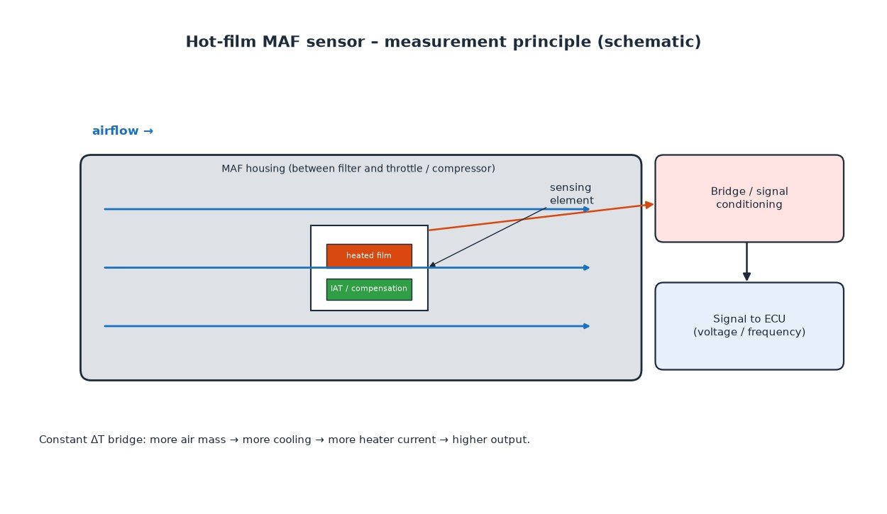
Hot-wire and hot-film measurement
Both common designs heat a sensing element in the airstream and use cooling by the flow as the measurement principle.
Hot-wire
Early designs used a thin platinum wire heated electrically. Airflow cools the wire. The electronics either hold the wire at constant temperature by adjusting current, or hold current and watch temperature change. Heating power — or the resulting voltage — rises with mass flow. Hot-wire elements are fragile and contamination-sensitive, so production cars moved largely to hot-film designs.
Hot-film (HFM)
A hot-film MAF uses a micromachined sensing chip or ceramic substrate with thin-film heaters and temperature sensors. One region is heated; another measures incoming air temperature for compensation. A bridge keeps the heated film at a fixed temperature difference above the intake air. The current (or derived voltage or frequency) needed to hold that difference tracks air mass flow.
Many modules output an analogue voltage that rises with flow; others use frequency or a digital protocol. The ECU converts the raw signal with a transfer characteristic into air mass. Intake air temperature (IAT) is often integrated in the same housing so density compensation and diagnostics share one connector.
Where the MAF sits in the intake
The MAF housing sits between the air filter and the throttle body (petrol) or the turbo compressor inlet (many turbo engines). It must see the full stream of air that will enter the engine. Any air that joins after the sensor — a split hose, cracked boot, loose clamp, or a PCV path into the manifold — is unmetered air. The ECU under-reads mass flow while the engine burns more oxygen than expected, which often shows as a lean mixture, rough idle or limiters that do not match the logged MAF.
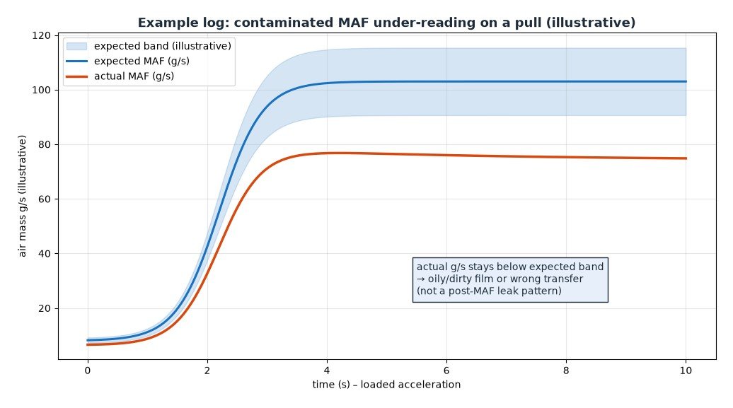
Oil mist from crankcase ventilation, a poorly designed catch can, or a dirty filter can coat the sensing film. A coated film changes heat transfer and usually under-reads.
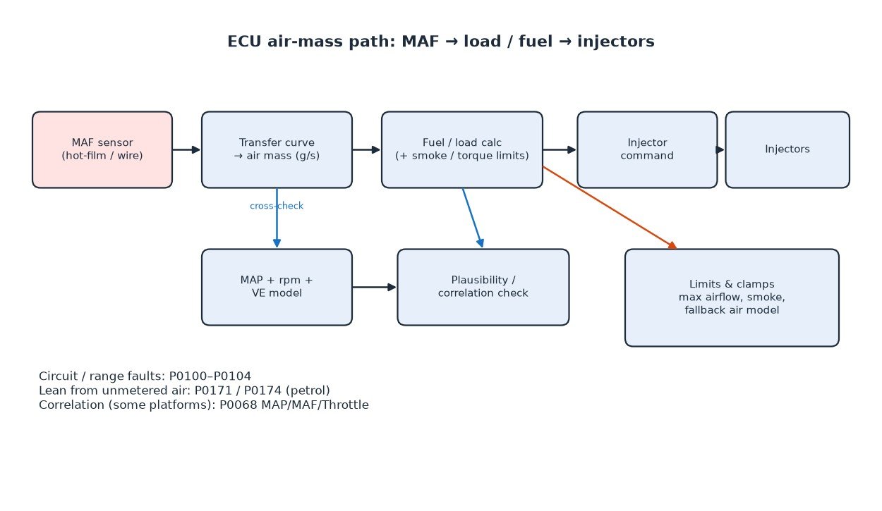
How the ECU uses air mass
On a typical MAF-based petrol engine, measured air mass is the primary input for base fuel quantity. The ECU multiplies air mass by the reciprocal of the desired air–fuel ratio, then applies short- and long-term fuel trims from the oxygen sensors. Load is often a normalised air charge from MAF and engine speed.
Many ECUs also cross-check MAF against a speed-density estimate from MAP, rpm and volumetric efficiency. Persistent disagreement can set correlation faults (for example P0068 on some platforms) or force a fallback that ignores the MAF. On diesels that retain a MAF, air mass still limits smoke and supports air-path modelling even when injection quantity is commanded more directly from pedal and torque maps. Some light vans keep a MAF for the same reasons; many heavy-duty diesels rely more on MAP-based estimation.
Contamination, leaks and wiring faults
Field failures cluster into a few patterns:
- Contamination: oil or dirt on the film lowers reported mass flow. Sensor-safe cleaner sometimes restores function; a heavily coated or scratched film needs replacement.
- Post-MAF intake leaks: unmetered air after the sensor. Lean codes (P0171 / P0174 on many petrol banks), unstable idle and a MAF that looks low for the observed power are classic clues. A smoke test downstream of the MAF finds these leaks.
- Wiring and supply faults: open signal, short to ground or voltage, poor 5 V reference, or high resistance in the ground. These produce the P0100-family circuit codes.
- Wrong or drifting transfer curve: a sensor that still outputs a voltage but no longer matches calibration, often after contamination or an incorrect replacement part.
A practical diagnostic approach
Start with freeze-frame and live data, not with a new sensor.
- Note the exact code. P0100 is a general circuit fault; P0101 range/performance; P0102 low; P0103 high; P0104 intermittent. An integrated IAT code (P0110–P0114) alongside often points to the shared connector or harness.
- Compare MAF g/s with expected values. At hot idle a healthy small petrol sits in a modest g/s band; under a full-load pull the reading should rise smoothly with rpm and load. Compare against a known-good log or a MAP-based estimate.
- Inspect the intake path: filter, oil film on the element, cracked boots after the MAF, clamps, and aftermarket pipework.
- Smoke-test for post-MAF leaks before condemning the sensor when lean trims or low power accompany a “low” MAF reading.
- Check power, ground and signal against the manufacturer pinout. A missing 5 V reference can take out several sensors at once.
Related fault codes (DTCs)
Generic OBD-II (SAE J2012) codes related to mass air flow sensing, the integrated intake air temperature sensor often built into the MAF housing, lean mixture from unmetered air, and MAP/MAF/throttle correlation. Exact wording and enable conditions vary by manufacturer.
| Code | Meaning | Typical causes |
|---|---|---|
| P0100 | Mass or Volume Air Flow "A" Circuit | Open/short in MAF signal circuit, unplugged connector, failed sensor, wiring damage |
| P0101 | Mass or Volume Air Flow "A" Circuit Range/Performance | MAF reading implausible vs rpm/MAP/throttle: contaminated film, intake leak after MAF, skewed transfer curve, wrong sensor |
| P0102 | Mass or Volume Air Flow "A" Circuit Low | Signal open or shorted to ground, failed sensor, poor ground, severe contamination causing very low output |
| P0103 | Mass or Volume Air Flow "A" Circuit High | Signal shorted to voltage, open ground, failed sensor |
| P0104 | Mass or Volume Air Flow "A" Circuit Intermittent | Loose connector pins, chafed harness, intermittent supply or ground |
| P0110 | Intake Air Temperature Sensor "A" Circuit | IAT circuit fault (often integrated in the MAF housing): open/short, failed element, shared connector issue |
| P0111 | Intake Air Temperature Sensor "A" Circuit Range/Performance | IAT reading implausible vs ECT/ambient after soak, contaminated or failed IAT element in MAF housing |
| P0112 | Intake Air Temperature Sensor "A" Circuit Low | IAT signal shorted to ground or failed low |
| P0113 | Intake Air Temperature Sensor "A" Circuit High | IAT signal open or shorted to voltage (common when MAF/IAT connector is unplugged) |
| P0114 | Intake Air Temperature Sensor "A" Circuit Intermittent | Loose pins or damaged harness at the MAF/IAT connector |
| P0171 | System Too Lean (Bank 1) | Unmetered air after the MAF (intake leak), low fuel pressure, exhaust leak before O2 sensor, contaminated MAF under-reading |
| P0174 | System Too Lean (Bank 2) | Same lean causes on bank 2: post-MAF leak, fuel delivery, or MAF under-read on V-engines |
| P0068 | MAP/MAF – Throttle Position Correlation | MAF, MAP and throttle disagree: post-MAF leak, contaminated or failed MAF, MAP fault, throttle body / TPS issue |
What this means for tuning
Calibration on a MAF-equipped ECU almost always touches air-mass scaling, airflow clamps and the fuel or torque maps that use the result. Raising requested fuel or torque without keeping the MAF path and its limits consistent with real airflow can hit a max airflow clamp, force a fallback model, or set range/performance faults under load.
On diesels that use MAF for smoke limiting, an under-reading contaminated sensor can cut fuel early and feel like a weak file. An over-scaled MAF can allow more fuel than intended. After changes, log MAF g/s with MAP, rpm and commanded fuel on a full-load pull, and keep the transfer and clamps matched to the hardware. Work from the specific ECU definition and measured data — not invented map values.
Key takeaway
A MAF reports air mass by measuring how hard it is to keep a heated film or wire at temperature in the intake stream. The ECU turns that into fuel, load and limiters, and cross-checks it against MAP where available. Most real-world faults are contamination, unmetered air after the sensor, or wiring. Diagnose with live g/s versus expected load, a smoke test and a power/ground check, and keep calibration aligned with what the sensor and clamps can report.
Need a calibration that respects real airflow measurement? Order your tuning file from ECUFileMarket.