
On almost every modern car there is no cable between your foot and the throttle plate. An accelerator pedal position (APP) sensor reports what you want, the engine control unit (ECU) decides how much air the engine should get, and a small electric motor moves the throttle plate while position sensors confirm where it is. This is electronic throttle control (ETC), or drive-by-wire. Here is how it works, why it drops into limp-home mode, and how to diagnose it properly.
The parts of an electronic throttle system
- Accelerator pedal module – a pedal arm with a sensor that has two independent output tracks (APP 1 and APP 2), with no mechanical link to the engine.
- Electronic throttle body – a butterfly plate on a shaft, turned by a DC motor through a reduction gear train, with springs on the shaft and a two-track throttle position sensor (TPS 1 and TPS 2).
- ECU – reads all four tracks, calculates a target angle and drives the motor through an H-bridge output stage with a PWM signal, so it can push the plate open or pull it closed.
How the throttle body holds position
The motor works against a spring package. On most designs one spring tries to close the plate and another stops it at a slightly open default (limp-home) position. With the motor unpowered, the plate rests there. To open further, the ECU drives the motor one way; to close tighter for idle or overrun, it drives it the other way. The motor is therefore controlled continuously, not just switched on and off.
Older sensors used potentiometer wipers on a resistive track. Many current throttle bodies and pedals use contactless Hall-effect or inductive sensors that do not wear the same way, and some send position digitally (for example via SENT) instead of as analogue voltages. The redundancy principle stays the same.
Why two tracks on the pedal and throttle?
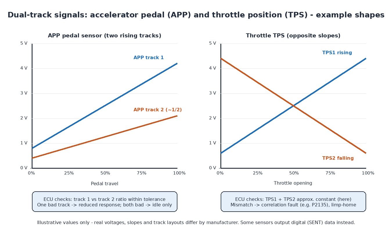
With no cable as backup, the ECU must never trust a single faulty signal. A common pedal layout has two rising signals, one roughly half the other. A common throttle layout has one signal rising and one falling as the plate opens. The ECU continuously checks that both tracks agree within a calibrated tolerance; a short, a worn track or a corroded pin makes one signal move differently and the correlation check catches it. Many pedals also give each track its own 5 V reference and ground, so one wiring fault cannot pull both tracks the same way.
Closed-loop control inside the ECU
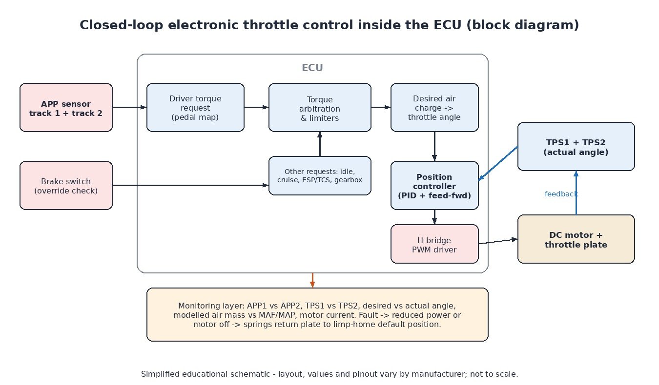
Engine management is torque-based. The pedal signal becomes a driver torque request through a pedal map, then is arbitrated with idle control, cruise control, stability/traction interventions, gearbox requests and protection limiters. The result becomes a desired air charge and finally a target throttle angle. A position controller (typically PID-style with feed-forward to compensate for springs and friction) compares target and measured angle and corrects the motor drive many times per second. Monitoring functions check the tracks, desired versus actual angle, motor current and whether measured airflow (MAF or MAP) is plausible. Many vehicles also apply a brake override when brake and accelerator are pressed together.
Limp-home mode
- One pedal track faulty – the engine may run on the remaining track with limited power or slow response.
- Both pedal tracks implausible – typically a fixed elevated idle; the pedal is ignored.
- Throttle sensor or motor fault – the ECU may switch the motor off, the springs return the plate to its default angle, and engine speed is controlled with fuel and ignition, often with an rpm limit.
Limp-home is meant to get the vehicle off the road, not to keep driving. A warning lamp and stored code always come with it.
Diagnostics that find the real fault
- Read codes and freeze frame. Note circuit low/high, range/performance or correlation, and the sensor letter. Letters (“A”, “B”, “D”, “E”…) are assigned by the manufacturer, so check whether the code means pedal or throttle.
- Compare live data. Key on, engine off: press the pedal slowly and confirm both APP values move smoothly and in proportion. Then compare desired and actual throttle angle at idle and during gentle revving.
- Scope both tracks together. A two-channel sweep shows dropouts on a worn track that slow scan-tool data can miss.
- Check references, grounds and wiring. Measure the 5 V supplies and grounds at the connector, voltage-drop the motor circuit under load, and look for water ingress and chafed harnesses.
- Inspect the plate and bore. Carbon and oil residue (from crankcase ventilation and, on diesels, EGR) can make the plate stick. Clean with the ignition off and connector unplugged, and do not force the plate by hand where the manufacturer warns against it.
- Run the adaptation. After cleaning or replacing parts, most ECUs need a throttle learn to relearn end stops and idle airflow.
Cars, vans, trucks, tractors and motorcycles
Petrol cars and vans use the electronic throttle as the main load control. On diesels the pedal has been electronic for a long time, while the intake throttle mainly supports smooth shutdown, EGR flow and exhaust temperature management. Heavy trucks use the same dual-track pedal logic alongside engine and exhaust brake controls. Many tractors combine a foot pedal with an electronic hand-throttle lever. Ride-by-wire motorcycles read a twistgrip sensor with redundant tracks, enabling riding modes, cruise control and traction control.
Related fault codes (DTCs)
Generic SAE J2012 codes; sensor letters and manufacturer codes vary, so confirm with service data.
| Code | Meaning | Typical causes |
|---|---|---|
| P0121 | Throttle/Pedal Position Sensor/Switch “A” Circuit Range/Performance | Worn track, signal implausible versus airflow, sticking plate |
| P0122 / P0123 | Throttle/Pedal Position Sensor/Switch “A” Circuit Low / High | Short to ground / voltage, open reference or ground |
| P0222 / P0223 | Throttle/Pedal Position Sensor/Switch “B” Circuit Low / High | Wiring fault on second track, failed sensor |
| P2122 / P2127 | Throttle/Pedal Position Sensor/Switch “D” / “E” Circuit Low | Often pedal tracks: wiring, connector, pedal sensor |
| P2135 | Throttle/Pedal Position Sensor/Switch “A”/”B” Voltage Correlation | Worn throttle sensor, high-resistance pin, water in connector |
| P2138 | Throttle/Pedal Position Sensor/Switch “D”/”E” Voltage Correlation | Worn pedal sensor, wiring or reference fault |
| P2101 | Throttle Actuator “A” Control Motor Circuit Range/Performance | Carboned plate, worn gears, motor or circuit fault |
| P2111 / P2112 | Throttle Actuator Control System – Stuck Open / Stuck Closed | Binding, carbon, ice, damaged gear train |
| P0638 | Throttle Actuator Control Range/Performance (Bank 1) | Desired and actual angle differ |
What it means for tuning
Pedal maps and torque request tables can be calibrated to change response, but plausibility checks, brake override and throttle monitoring are safety functions and must never be disabled. Fix sticking throttle bodies and pedal faults first – a remap cannot cure a mechanical or wiring problem.
Want a tested calibration that keeps all throttle safety monitoring intact? Browse the tuning file catalogue at ECUFileMarket.