
Every time a scan tool reads fault codes from a modern car, or a flasher writes a new file to an engine ECU, the two devices are almost always speaking the same language: Unified Diagnostic Services, better known as UDS and standardised as ISO 14229. You do not need to read hex to remap a car, but knowing what UDS does explains a lot of everyday workshop behaviour: why an ECU refuses a command, why a write needs a stable battery voltage, and why some ECUs can be read over the diagnostic port while others need a bench connection. This article walks through the protocol in practical terms.
What UDS is, and what it is not
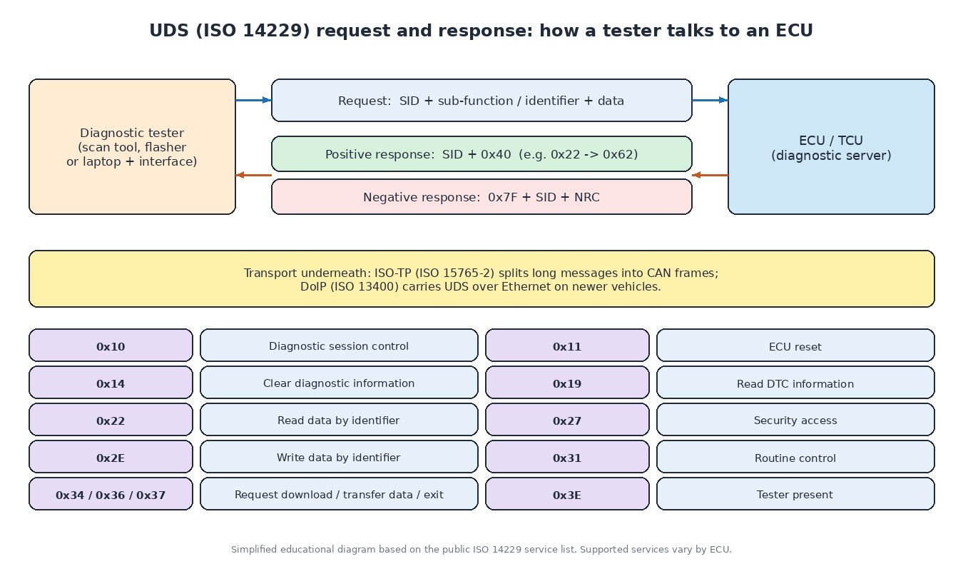
UDS is an application-layer protocol. It defines what the tester asks and how the ECU answers, not how the bits travel. Underneath it sits a transport layer: on most vehicles that is CAN with ISO-TP (ISO 15765-2), which splits long messages such as a list of fault codes or a block of flash data into individual CAN frames and reassembles them. Newer platforms also carry UDS over Ethernet using DoIP (ISO 13400), which is much faster for programming large ECUs. Older protocols like KWP2000 work on similar principles, and UDS borrowed many of their ideas.
UDS is also not the same as generic OBD-II. The emissions-related “modes” every scan tool understands (live data, stored codes, readiness) come from SAE J1979 / ISO 15031-5. UDS is the much wider manufacturer diagnostic layer behind it: coding, adaptations, actuator tests, security, and programming. On heavy-duty trucks you will often meet SAE J1939 messages for engine data and fault reporting, but many truck and off-highway controllers also accept UDS for workshop diagnostics and flashing.
The request and response pattern
The tester is the client and the ECU is the server. Each request starts with a one-byte service identifier (SID), followed by a sub-function or data identifier and any data. The ECU replies in one of two ways:
- Positive response: the SID plus 0x40. A request with 0x22 (read data by identifier) comes back as 0x62 with the requested value.
- Negative response: 0x7F, the SID that was refused, and a negative response code (NRC) that says why.
The services workshop tools use most often are session control (0x10), ECU reset (0x11), clear diagnostic information (0x14), read DTC information (0x19), read data by identifier (0x22), security access (0x27), write data by identifier (0x2E), input/output control (0x2F) for actuator tests, routine control (0x31), the download trio 0x34/0x36/0x37 and tester present (0x3E).
Sessions and security access
An ECU starts in the default session, where only harmless services are allowed. To do more, the tester switches to an extended session (for coding, adaptations and actuator tests) or a programming session (for flashing). While a non-default session is active, the tester keeps sending tester present (0x3E); if it stops, the ECU times out and drops back to the default session.
Sensitive services are locked behind security access (0x27). The tester asks for a “seed”, the ECU returns a value, and the tester must answer with the correct “key” calculated by an algorithm the manufacturer keeps private. A wrong key returns NRC 0x35 (invalid key); too many wrong keys return 0x36 and a lock-out delay, signalled by 0x37 until the time has passed. Many newer ECUs add further protection on top, such as signed software and secure boot, which is why OBD access is not possible on every ECU and tools fall back to bench, boot or BDM methods. We cover those in ECU reading methods explained.
How flashing works over UDS
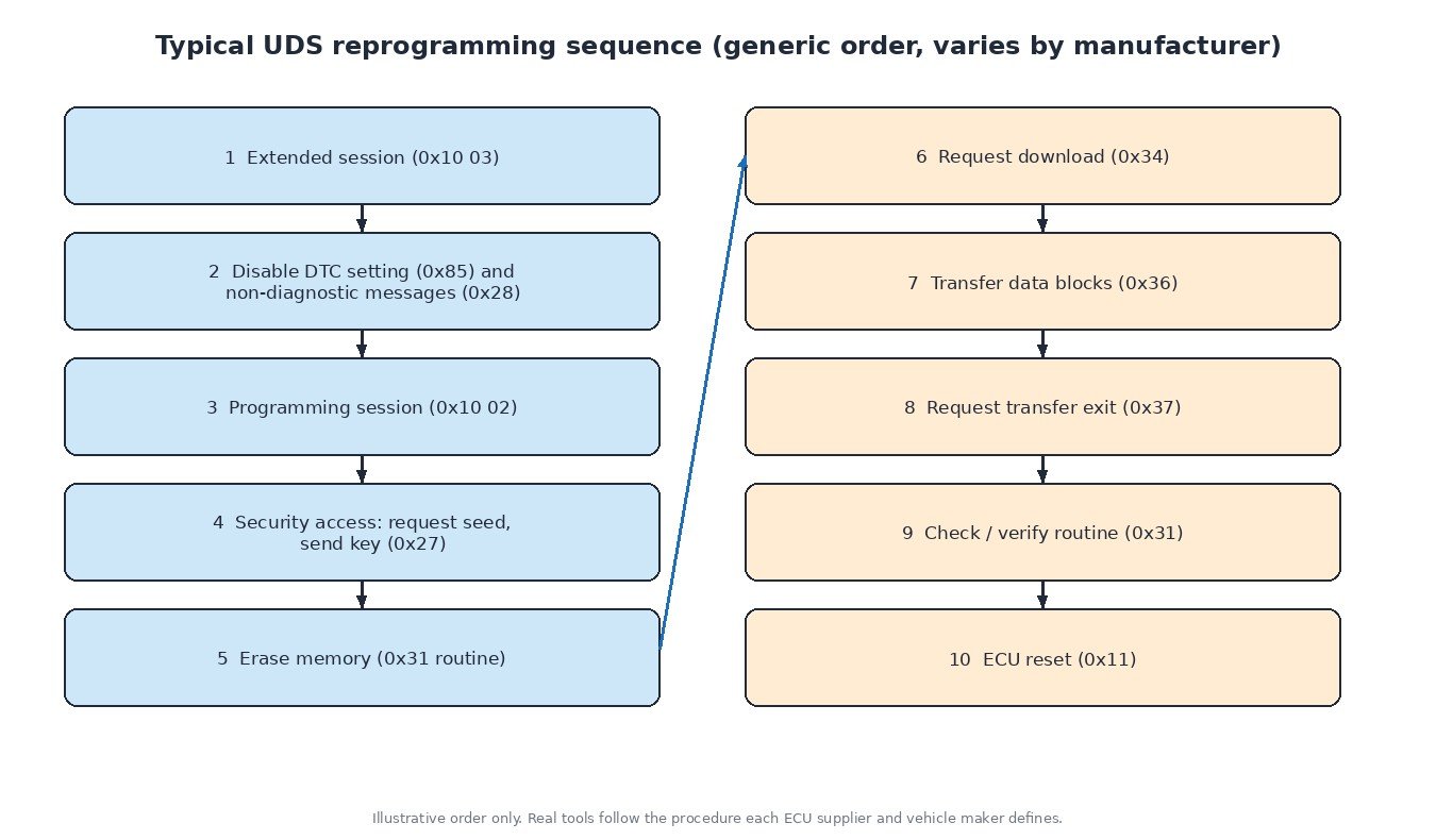
Reprogramming follows a fairly standard pattern, although every vehicle maker defines its own exact procedure. The tool enters the extended session, usually turns off fault code setting (0x85) and normal network messages (0x28) so other modules stay quiet, then moves to the programming session and unlocks security access. Next it starts an erase routine with routine control, announces the download with request download (0x34), sends the data in numbered blocks with transfer data (0x36) and closes with request transfer exit (0x37). A check routine then lets the ECU verify what it received before an ECU reset (0x11) starts the new software.
This is why a flash needs a stable power supply and an uninterrupted connection: if the process stops between erase and verification, the ECU may be left without valid software. Our guide on recovering from a failed ECU write covers what to do then. The ECU’s own verification also explains why a modified file must carry correct checksums before it is written; see how ECU checksums work.
Reading fault codes the UDS way
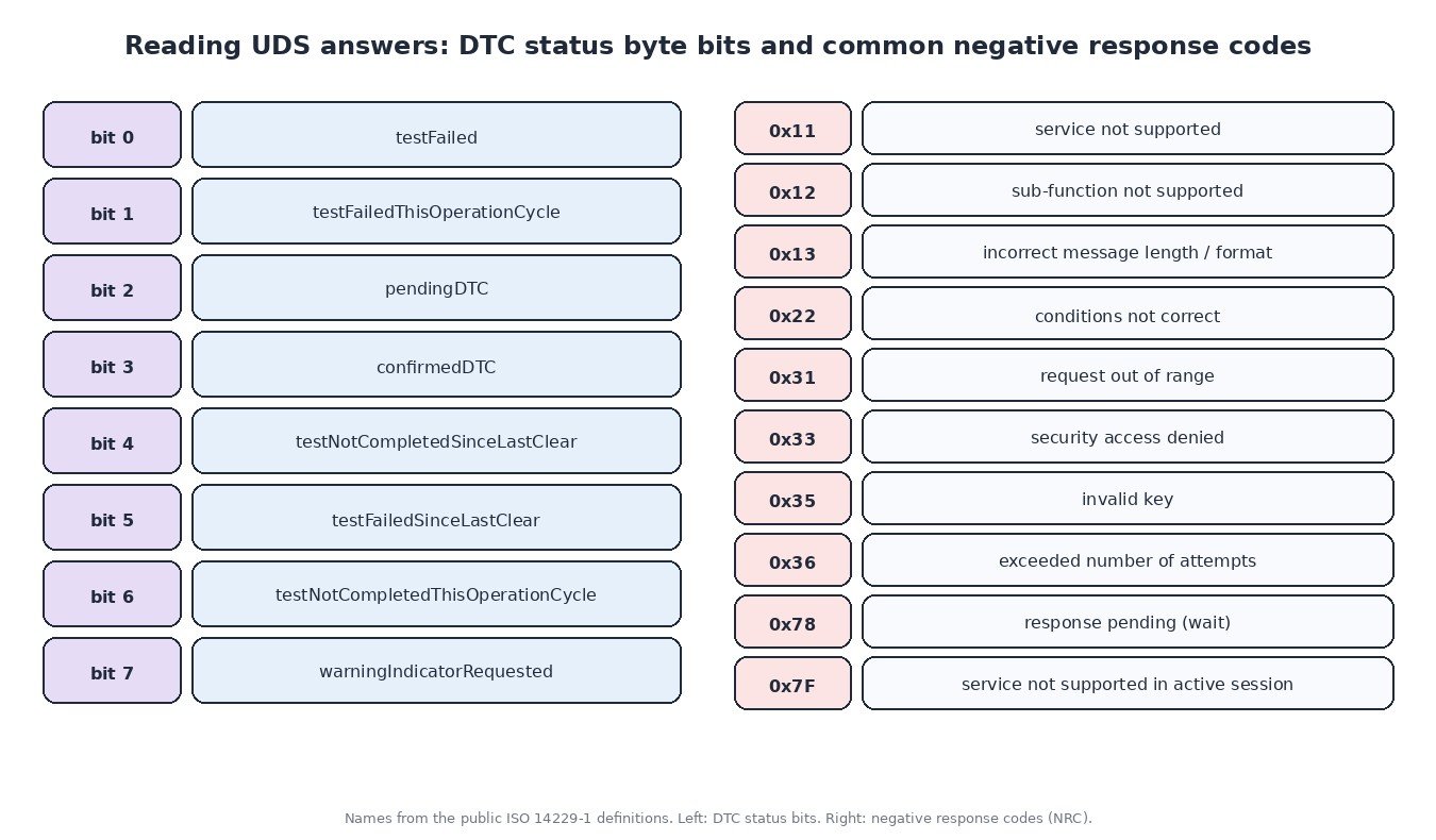
Service 0x19 returns each DTC as three bytes plus a status byte. Each bit of that byte means something specific: bit 0 testFailed (failing right now), bit 2 pendingDTC, bit 3 confirmedDTC, bit 7 warningIndicatorRequested (the ECU wants the warning lamp on), and so on. A code with “pending” set but not “confirmed” failed once but has not yet matured. A code with “testNotCompletedSinceLastClear” set tells you the monitor has not run since the last clear, so a clean result is not yet proven. Reading these bits stops you from chasing old history or declaring a repair fixed too early.
Workshop tips: what common NRCs are telling you
- 0x22 conditions not correct: the ECU wants something first, often engine off, vehicle stationary, or a specific session. Check ignition state and speed.
- 0x7F service not supported in active session: you are in the wrong session for that request.
- 0x33 security access denied or 0x35 invalid key: the tool’s seed/key handling does not match this ECU or software version.
- 0x78 response pending: not an error. The ECU is busy (for example erasing flash) and will answer later. Do not interrupt.
- No response at all: check power, ground, the gateway and the CAN lines before blaming the ECU. Our article on how CAN bus works explains the basic measurements.
Always use a battery support unit during long sessions and programming, and save a full original read before any write.
Related fault codes (DTCs)
These generic SAE codes often appear around diagnostic communication, gateway problems and programming. Manufacturer-specific codes may add more detail.
| Code | Meaning | Typical causes |
|---|---|---|
| U0001 | High speed CAN communication bus | Open or shorted CAN-H/CAN-L wiring, missing or wrong termination, a module pulling the bus down, water in connectors |
| U0073 | Control module communication bus “A” off | Bus-off condition after repeated errors: shorted bus lines, faulty transceiver in one module, poor ground or supply |
| U0100 | Lost communication with ECM/PCM “A” | Engine ECU without power or ground, blown fuse or main relay, CAN wiring fault at the ECU, ECU left in a bad state after flashing |
| U0101 | Lost communication with TCM | Transmission controller supply, ground or CAN wiring fault, failed or unprogrammed TCM |
| U0121 | Lost communication with anti-lock brake system (ABS) control module | ABS module power or ground, CAN wiring or connector corrosion, failed module |
| U0140 | Lost communication with body control module | BCM supply or ground, CAN wiring fault, low battery voltage during testing |
| U0155 | Lost communication with instrument panel cluster (IPC) control module | Cluster power or ground, CAN wiring or gateway fault, failed cluster |
| U0300 | Internal control module software incompatibility | Modules with mismatched software versions, wrong file or variant coding after replacement or programming |
| U0401 | Invalid data received from ECM/PCM “A” | Engine ECU sending implausible values, ECU internal fault, software mismatch between modules |
| P0601 | Internal control module memory check sum error | Corrupted or modified flash content with an incorrect checksum, interrupted programming, internal ECU fault |
| P0602 | Control module programming error | ECU not programmed or programming incomplete, wrong software, variant coding missing |
| P0603 | Internal control module keep alive memory (KAM) error | Loss of permanent battery feed, battery disconnected or flat, internal ECU fault |
| P0604 | Internal control module random access memory (RAM) error | Internal ECU hardware fault, supply voltage problems |
| P0605 | Internal control module read only memory (ROM) error | Corrupted program memory, failed programming, internal ECU fault |
| P0606 | Control module processor | Internal processor or monitoring fault, poor supply or ground, water damage, sometimes fixed by a software update |
Generic SAE J2012 code meanings shown. Exact wording and enable conditions vary by manufacturer; always check service data.
Have an original ECU read ready? Upload it to ECUFileMarket and get a tuning file prepared for your exact hardware and software version.