
Almost every modern tractor above the smallest compact class can drive all four wheels, and most have at least one differential lock. Years ago the operator engaged these with a lever and remembered to release them before a turn. Today a solenoid valve does the work and the tractor or transmission ECU decides, based on speed, steering angle, brakes and hitch position, when front-wheel drive and the locks are on. That makes the machine easier to drive, but it also means a “4WD fault” can be a sensor, a wire, a pressure problem or a mechanical failure. This article explains how the system works and how to diagnose it.
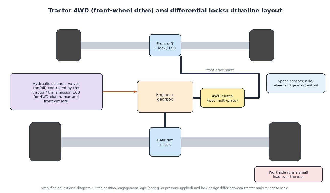
What front-wheel drive and diff locks do
On most tractors the rear axle is driven all the time. Front-wheel drive (often called MFWD or 4WD) is added through a clutch that connects a shaft from the gearbox to the front axle. When it is engaged, the front wheels pull as well, which improves traction in the field and on slopes and lets the tractor use all four wheels for braking.
A normal differential lets the left and right wheels turn at different speeds, which is needed in corners. The downside is that if one wheel loses grip, most of the torque goes to that wheel and the tractor stops moving. A differential lock joins both sides so they turn together. Rear diff locks are common on almost all tractors; many front axles have either a lockable differential or a limited-slip design instead.
The hardware: clutches, locks and valves
The front-wheel drive clutch is usually a wet multi-plate pack running in transmission oil. A design used by many manufacturers holds this clutch closed with springs and opens it with oil pressure. The benefit is fail-safe behaviour: if pressure is lost or the engine is stopped, front-wheel drive stays engaged and the tractor keeps four-wheel braking. Other designs work the other way round, so always check which logic your machine uses before diagnosing.
Differential locks are normally engaged by a hydraulic piston that pushes a dog clutch or a small plate pack. They usually need pressure to engage, so with no pressure the differential stays open. Each function is controlled by an on/off solenoid valve on a valve block, often with a pressure switch or a test port so the workshop can check that oil really arrives. On trucks the idea is similar, but cross-axle and inter-axle locks are typically operated by air through solenoid valves rather than by oil.
How the automatic management works
The ECU reads several inputs and releases or engages the functions according to rules stored in its calibration:
- Speed: above a speed set by the manufacturer, front-wheel drive and the diff locks are released to protect the driveline and tyres on the road.
- Steering angle: a steering angle sensor on the front axle tells the ECU when the wheels are turned. Beyond a certain angle the diff lock releases so the tractor can turn, then it can re-engage when the wheels straighten.
- Brakes: when both brake pedals are pressed together, many tractors engage front-wheel drive so all four wheels brake.
- Hitch position: headland management can release the locks and front-wheel drive when the electronic hitch is raised and restore them when it is lowered again.
- Speed signals: axle, wheel and ground speed signals let the ECU compare front and rear speeds and detect implausible values.
Thresholds such as speed and steering angle differ by model and on many tractors can be adjusted in the terminal or with a service tool.

Front axle lead and tyres
When front-wheel drive is engaged, the two axles are mechanically connected. The gear ratios are chosen so the front wheels travel slightly faster than the rear, usually a small lead of a few percent. This helps the front axle pull rather than push. If the tyres are changed to a combination the manufacturer did not approve, or pressures are very different, the lead can become too large or even negative. The result is tyre wear, a driveline that “winds up” on hard ground, and extra load on the front-wheel drive clutch. The ECU may also see front and rear speeds that do not match what it expects and set a plausibility fault.
Common symptoms
- Front-wheel drive indicator does not come on, or the front axle does not pull in the field.
- Front-wheel drive will not release, giving tyre scrub and tight turns on hard surfaces.
- Diff lock does not engage, or does not release when turning.
- Warning lamp with codes for a solenoid, pressure switch, steering angle or speed sensor.
- Banging or vibration from the driveline, which can point to clutch wear or wrong tyre sizes.
Diagnosis step by step
- Read the codes. On J1939 tractors note the SPN and FMI. FMI 5 or 6 on a solenoid usually means an open or shorted circuit; FMI 2 on a speed sensor means an erratic signal. Our guide to J1939 fault codes explains the format.
- Note the conditions. Which mode was active (manual or automatic), the speed, steering angle and whether the hitch was up.
- Check the solenoid circuit. Measure coil resistance against service data, inspect connectors for corrosion and check that the ECU output switches when commanded.
- Measure pressure. Fit a gauge at the test port and confirm the pressure follows the command and does not drop off. Low pressure points to oil level, filter, seals or the valve itself.
- Check the inputs in live data. Steering angle, brake switches, pressure switches and axle speeds should all read sensibly. A steering angle sensor often needs calibration after axle or sensor work.
- Look at the mechanics last. If electrics and pressure are correct, the clutch pack or lock may be worn and need repair.

What this means for engine tuning
Front-wheel drive and diff lock rules live in the tractor or transmission controller, not in the engine calibration. Engine tuning does not change them, but more torque means more load on the front-wheel drive clutch, the diff locks and the axles, especially when the tractor works in 4WD with full traction. A responsible file keeps the engine and transmission torque limits and protections working, keeps torque gains moderate for heavy draft work, and is always built from a full original read of the ECU. Keep a complete backup before any change.
Related fault codes (DTCs)
Tractor makers use many of their own codes for 4WD and diff lock solenoids. The table shows standard J1939 SPNs and generic SAE codes that are often involved in these faults. The FMI number after the SPN tells you the failure type.
| Code | Meaning | Typical causes |
|---|---|---|
| SPN 904 (+FMI) | Front axle speed | Axle speed sensor fault, damaged or dirty tone wheel, wiring or connector problem, signal implausible against rear axle speed |
| SPN 905 (+FMI) | Relative speed, front axle, left wheel | Wheel speed sensor or air gap problem, tyre size difference, wiring fault |
| SPN 906 (+FMI) | Relative speed, front axle, right wheel | Wheel speed sensor or air gap problem, tyre size difference, wiring fault |
| SPN 191 (+FMI) | Transmission output shaft speed | Output speed sensor fault, sensor gap, damaged target wheel, wiring or connector problem |
| SPN 84 (+FMI) | Wheel-based vehicle speed | Speed source missing or erratic on the network, sensor fault, CAN communication problem |
| SPN 1862 (+FMI) | Wheel-based machine speed (ISOBUS) | Wheel or gearbox speed signal fault, wrong rolling circumference calibration |
| SPN 1859 (+FMI) | Ground-based machine speed (ISOBUS) | Radar or GNSS speed source fault, dirty or misaimed radar, wiring problem |
| SPN 168 (+FMI) | Battery potential / power input 1 | Weak battery, charging fault, poor ground or supply connection, causing solenoid and sensor faults |
| P0500 | Vehicle speed sensor “A” | Speed sensor fault, damaged tone ring, wiring, implausible signal |
| P0562 | System voltage low | Battery or alternator problem, high resistance in supply or ground circuits |
| P0700 | Transmission control system (MIL request) | The transmission ECU has stored its own fault code; read the transmission module for details |
Standard SAE J1939 / ISO 11783 parameter names and generic SAE J2012 code meanings shown. Exact wording and manufacturer codes vary; always check service data.
Need a tuning file for your tractor or machine built on your original ECU read? Upload it to ECUFileMarket and get a file prepared for your exact hardware and software version.