
An automatic gearbox does not shift by magic. A Transmission Control Unit (TCU / TCM) reads speed, range, temperature and engine torque, then commands hydraulic pressure and shift solenoids so the correct clutch packs engage at the right time. This technician guide covers how a conventional torque-converter automatic works, what the sensors and solenoids do, limp mode behaviour, and how dual-clutch and agricultural powershift/CVT systems differ—on cars, vans, trucks, ag machines and bikes that use AT or DCT hardware.
What the TCU actually controls
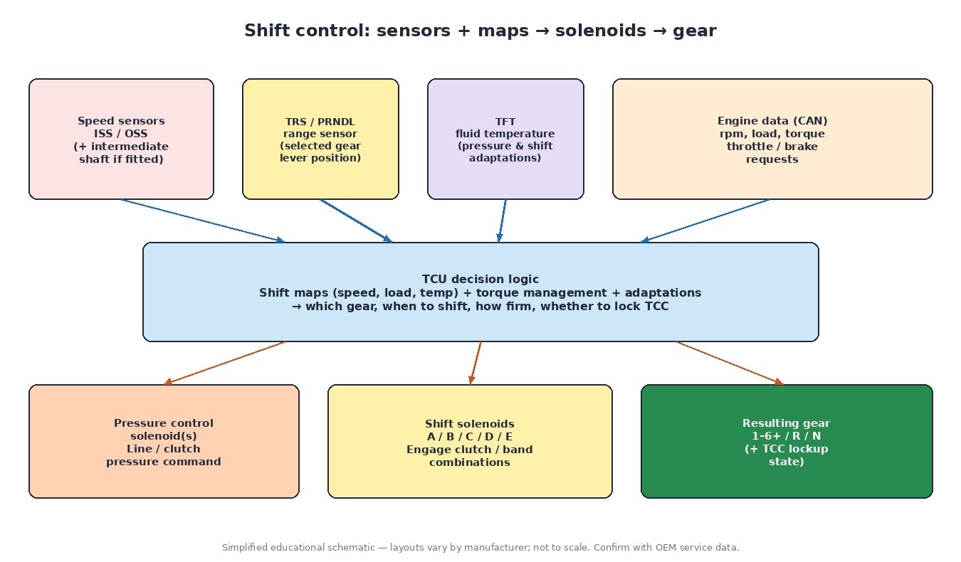
On a classic planetary automatic, engine torque enters a torque converter, then a gearbox with clutch packs selected by a valve body. The TCU decides gear, shift timing, shift firmness and torque-converter clutch (TCC) lockup by driving shift solenoids and one or more pressure control solenoids, using maps that combine vehicle speed, load, fluid temperature and driver demand. Many platforms also request engine torque reduction over CAN during shifts so the clutches are not overloaded.
Torque converter and lockup clutch
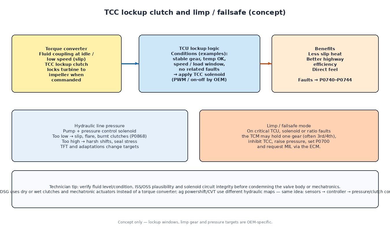
The torque converter is a fluid coupling. At idle and low speed the impeller and turbine slip, which multiplies torque and allows the vehicle to stop in gear. That slip also generates heat. When conditions allow—stable gear, adequate transmission fluid temperature (TFT), and a calibrated speed/load window—the TCU applies the TCC lockup clutch so the turbine locks to the impeller. Lockup improves highway efficiency and reduces fluid heating. Faults in the TCC circuit or performance monitors commonly set codes in the P0740–P0744 range. Lockup windows and PWM versus on/off control are manufacturer-specific—confirm enable conditions in service information.
Hydraulic line pressure and shift solenoids
A transmission pump supplies line pressure. The TCU modulates that pressure with a pressure control solenoid so clutch apply force matches demand: higher for firm, high-torque shifts; lower for comfort when load is light. Fluid that is low, burnt or the wrong specification changes real pressure versus commanded pressure and can trigger P0868 or harsh/flare symptoms. Shift solenoids (often labelled A–E in generic OBD) route fluid to the clutch elements that create each gear ratio. Electrical faults set circuit codes; sticking valves or worn clutch packs can set performance or incorrect gear ratio codes even when the wiring is fine.
Gear selection and shift maps
Shift maps are look-up strategies: for a given speed and load (and often TFT), the TCU chooses which gear to hold and when to upshift or downshift. Adaptive learning may firm or soften shifts over time. The transmission range sensor (TRS / PRNDL) tells the TCU which lever position the driver selected; mismatches between requested range and hydraulic state are a classic path for P0705–P0709.
Key sensors: ISS, OSS, TFT and engine speed
- Input / turbine speed sensor (ISS) — speed after the converter; used for shift scheduling, TCC slip and gear-ratio rationality.
- Output speed sensor (OSS) — output shaft speed; compared with ISS and commanded gear to detect slip or wrong ratio (P0730–P0736).
- TFT — fluid temperature; maps and pressure targets change with cold versus hot fluid (P0710–P0714).
- Engine speed input — from the ECM over CAN or a dedicated circuit (P0725–P0727); needed for converter slip and torque coordination.
Some designs add an intermediate shaft speed sensor (P0791–P0793). Always verify which sensor is which on the wiring diagram before replacing parts.
Limp and failsafe modes
On a critical solenoid, speed-sensor or ratio fault the TCU typically holds a single forward gear (often a mid gear such as 3rd or 4th—OEM specific), inhibits TCC, commands a safe pressure, sets P0700 (transmission control system MIL request) and asks the ECM to light the MIL. P0700 is the messenger—always read the TCM codes that caused it. Lost communication with the TCM (U0101) produces similar “no shift” complaints with a network or power/ground root cause.
DCT/DSG and agricultural powershift / CVT
Dual-clutch (DCT/DSG) units replace the torque converter with two dry or wet clutches and a mechatronic actuator block. The controller still uses speed sensors, temperature and shift maps, but actuation is clutch and fork control. Clutch overheat and mechatronic electrical faults dominate diagnostics.
Agricultural powershift and CVT transmissions use the same idea—sensors and maps driving hydraulic pressure and clutch packs or a variable element—but with different gear trains and much higher continuous torque. Use OEM hydraulic diagrams; do not assume passenger-car solenoid naming. Cars and vans dominate torque-converter and DCT volumes; trucks add heavy-duty coolers; some motorcycles use DCT or torque-converter automatics.
Related fault codes (DTCs)
Generic SAE J2012 definitions. Solenoid lettering, sensor placement and limp gear vary by manufacturer—confirm with service information.
| Code | Meaning | Typical causes |
|---|---|---|
| P0700 | Transmission Control System (MIL Request) | TCM has stored a fault; read TCM codes |
| P0705–P0709 | Transmission Range Sensor (PRNDL) circuit / performance | Misadjusted TRS, open/short, worn switch, linkage |
| P0710–P0714 | Transmission Fluid Temperature Sensor circuit / range | Failed TFT, wiring, stuck reading |
| P0715–P0717 | Input/Turbine Speed Sensor circuit / no signal | Failed ISS, air gap, tone wheel, connector |
| P0720–P0722 | Output Speed Sensor circuit / no signal | Failed OSS, wiring, tone ring damage |
| P0725–P0727 | Engine Speed Input circuit / no signal | Lost ECM rpm data, CAN or dedicated circuit fault |
| P0730 | Incorrect Gear Ratio | Clutch slip, low pressure, wrong fluid, ISS/OSS error |
| P0731–P0735 | Incorrect Gear Ratio (Gears 1–5) | Slip in that gear’s element, solenoid/valve body, pressure loss |
| P0736 | Incorrect Gear Ratio Reverse | Reverse clutch/band slip, low pressure, range error |
| P0740–P0744 | Torque Converter Clutch circuit / performance | TCC solenoid, wiring, stuck apply/release, fluid/valve issue |
| P0745 / P0746 / P0748 | Pressure Control Solenoid malfunction / performance / electrical | Failed PCS, wiring, pressure not tracking command |
| P0750–P0753 | Shift Solenoid A circuit / performance | Solenoid A electrical or mechanical fault, debris |
| P0755 / P0756 / P0758 | Shift Solenoid B malfunction / performance / electrical | Solenoid B circuit, stuck valve, hydraulic blockage |
| P0760 / P0765 / P0770 | Shift Solenoid C / D / E Malfunction | Corresponding shift solenoid electrical or mechanical fault |
| P0780 | Shift Malfunction | Pressure, solenoids, clutch wear, bad sensor data |
| P0791–P0793 | Intermediate Shaft Speed Sensor A circuit / no signal | Failed intermediate speed sensor or wiring (if equipped) |
| P0868 | Transmission Fluid Pressure Low | Low fluid, weak pump, leak, PCS fault, clogged filter |
| U0101 | Lost Communication With TCM | CAN wiring, TCM power/ground, failed TCM |
Diagnostic approach
- Read TCM and ECM codes; treat P0700 as a pointer to deeper TCM faults.
- Verify fluid level and condition with the OEM hot/cold procedure.
- Compare ISS, OSS and commanded gear on a road test; watch for flare.
- Check TRS/PRNDL agreement with the shifter and hydraulic range.
- Load-test solenoid circuits and inspect connectors at the case / mechatronics.
- For harsh or soft shifts, evaluate line-pressure command versus actual (where available) and TFT.
What it means for tuning
Engineered ECU or TCU files that raise torque must respect transmission torque limits, shift maps and TCC strategies. Raising engine torque without coordinated transmission calibration risks clutch slip, overheating and ratio codes. If shift quality changes after an engine remap, verify fluid, adaptations and TCU data before blaming the file alone.
Need an engineered remap that respects drivetrain limits? Order your tuning file from ECUFileMarket.