
Launch control is the strategy that lets a car leave the line as quickly as the tyres and driveline allow, without the driver having to balance throttle, clutch and wheelspin. On modern cars it is not a separate box: it is a set of functions spread across the engine ECU, the gearbox control unit (TCU) and the ABS/ESC module, all talking over CAN. This article explains what those functions do, which conditions must be met before launch control arms, and what calibration engineers and tuners need to keep in mind. It is a feature intended for closed tracks and motorsport events, not public roads.

What problem launch control solves
A standing start is a trade-off. Too little engine speed and a turbo engine is still off boost, so the car bogs. Too much and the tyres spin, or a clutch absorbs a large amount of energy as heat. The ideal is to release the drive at an engine speed where enough torque is available, then keep the driven wheels at a small, controlled amount of slip while the car accelerates. Launch control automates exactly that.
Enable conditions: when the system arms
Before the ECU allows a launch, it checks a list of conditions. The exact list is manufacturer-specific, but typical checks include:
- Vehicle stationary, confirmed by wheel speed signals from the ABS module.
- Brake pressed, read from the brake light switch and often brake pressure.
- Correct mode: a sport or track drive mode and, on many cars, ESC in a reduced or sport setting.
- Gear selected: drive or manual mode on an automatic or dual-clutch gearbox; on some manual cars the clutch pedal switch is used instead.
- Temperatures in range: engine oil, coolant and gearbox oil must be warm but not too hot.
- No relevant faults stored in the engine, gearbox, ABS/ESC or steering angle systems.
If one input is implausible, the system simply does not arm. That is why a weak brake switch or a wheel speed sensor fault can be the reason a customer says “launch control stopped working”. See our explanation of how the ECU uses brake and clutch pedal switches.
Holding the launch rpm
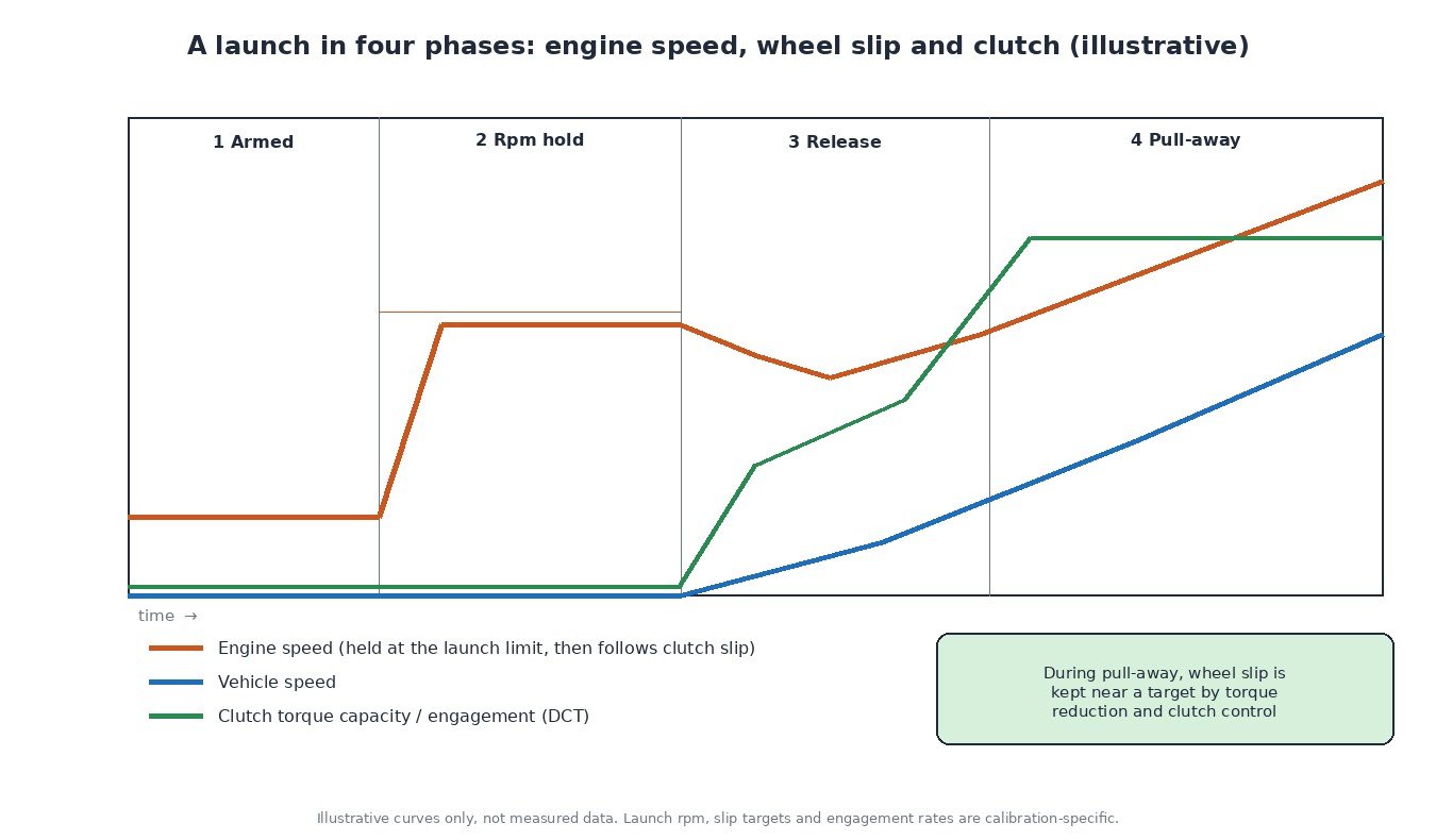
With the brake held and the accelerator pressed, the engine is allowed to rise to a launch engine speed rather than the normal rev limit. This is a separate, softer limiter. Instead of cutting fuel hard, most systems hold the speed with torque reduction through the torque model: ignition retard, throttle closing and, if needed, selective cylinder cut. The aftermarket often calls this a “two-step” limiter, because there is one limit for the launch and another for driving. The general principles of rev limiters are covered in our article on ECU limiters.
On turbo petrol engines, the hold phase is also used to bring boost up before the car moves. Some calibrations deliberately retard ignition so more energy goes into the exhaust and spins the turbine. This raises exhaust gas temperature and thermal load, which is one reason the manufacturer limits how long and how often the hold may last.
Release and pull-away
When the brake is released, the gearbox takes over the critical part of the launch.
- Dual-clutch gearbox: the TCU closes the clutch at a controlled rate, letting it slip while engine speed drops toward vehicle speed. Clutch torque capacity and engine torque are coordinated so the clutch neither locks too early nor slips for too long. Background: how dual-clutch transmissions work.
- Torque converter automatic: the brake holds the car while the converter slips; engine torque against the held brake builds converter output, then the brake is released.
- Manual gearbox: the driver controls the clutch; the ECU mainly holds the launch rpm and then manages wheel slip.
Once the car is moving, traction control compares driven wheel speeds with undriven ones (or with a vehicle speed estimate on all-wheel drive cars) and reduces engine torque to keep slip near a target. A small amount of slip gives the best acceleration; too much wastes energy as smoke.
Protection: counters, cool-down and torque limits
A launch is one of the highest load events a driveline sees. Clutches, driveshafts, differentials and tyres all take a peak load, and wet clutches heat their fluid. Manufacturers protect the hardware in several ways:
- a cool-down or lockout after several launches in a row;
- temperature-based disable thresholds for the gearbox and engine oil;
- torque limits per gear and during the launch phase, stored in both ECU and TCU;
- on some cars, logging of launch events in the control unit memory.
Diagnosis when launch control does not arm
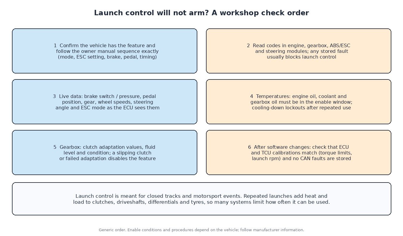
Start with the owner manual procedure, because the activation sequence is strict and differs between brands. Then read codes in all modules, not only the engine. In live data, check what the ECU actually sees: brake switch states, pedal position, gear, wheel speeds, steering angle, ESC mode and temperatures. On dual-clutch gearboxes, look at clutch adaptation values and fluid condition; a clutch that has lost adaptation or slips will usually disable launch control.
What this means for ECU and TCU tuning
Launch control sits at the meeting point of engine and gearbox calibration. Raising engine torque without considering the TCU torque limits and clutch capacity can lead to clutch slip codes or a disabled launch function, while a raised launch rpm increases clutch heat and driveline shock. A sound calibration keeps the ECU and TCU consistent, respects the hardware limits and leaves protections such as temperature lockouts and knock control active. Before any work, fix stored faults and confirm clutch adaptation is healthy. Our article on drive modes and multi-map calibrations explains how mode-dependent maps are organised.
Related fault codes (DTCs)
There is no generic code that means “launch control fault”. Instead, these codes point to inputs or systems that block or affect launch control:
| Code | Meaning | Typical causes |
|---|---|---|
| P0504 | Brake switch “A”/”B” correlation | Misadjusted or failing brake light switch, one switch contact not changing state, wiring or connector fault |
| P0571 | Brake switch “A” circuit | Faulty brake switch, blown fuse, open or shorted wiring; the ECU cannot confirm the brake is pressed |
| P0500 | Vehicle speed sensor “A” | Wheel speed sensor or tone ring fault, ABS module fault, missing speed signal on the network |
| P0219 | Engine overspeed condition | Engine speed exceeded the stored limit, for example a missed downshift, clutch slipping or a calibration fault |
| P0234 | Turbocharger/supercharger “A” overboost condition | Sticking wastegate or VGT, boost control solenoid or hose fault, boost sensor error, boost target too high for the hardware |
| P0325 | Knock sensor 1 circuit (bank 1 or single sensor) | Damaged sensor or connector, wiring fault, incorrect sensor torque; knock control falls back to a safe, retarded timing |
| P0811 | Excessive clutch “A” slippage | Worn clutch, failed clutch adaptation, low or degraded gearbox fluid on wet clutches, torque above the clutch capacity |
| P0700 | Transmission control system (MIL request) | The TCU has stored its own fault; read the gearbox module for the actual code |
| U0101 | Lost communication with TCM | CAN wiring or connector fault, TCU power or ground supply problem, failed TCU |
| U0121 | Lost communication with ABS control module | CAN wiring fault, ABS module power supply or ground fault, failed ABS module |
Generic SAE J2012 / ISO 15031-6 code meanings shown. Code support and descriptions vary by manufacturer; always confirm with service data for your vehicle.
Planning a performance or track calibration? Upload your original ECU or TCU read to ECUFileMarket and get a file prepared for your exact hardware and software version.