
Press the Sport button and the car suddenly feels sharper. Switch a motorcycle to Rain and the throttle turns soft. Select a power mode on a tractor terminal and the engine pulls harder in transport work. Behind every one of these buttons is the same idea: the control units carry more than one set of calibration data and switch between them on request. This article explains how drive modes and multi-map calibrations work, what they really change, how the signal travels through the vehicle network and what to keep in mind when you work on a file that contains several modes.

What a “mode” really is
An engine ECU, gearbox TCU or chassis module does not contain one map for each job but many maps that work together. A mode is simply a rule that tells the software which of several alternative maps, limiters or weighting factors to use. In some software the modes are complete parallel data sets; more often only a handful of maps have alternative versions while everything else is shared. The base engine protection, such as component temperature limits, smoke or lambda limits and turbo speed protection, normally stays the same in all modes.
If you are new to how maps are built, start with our guide to ECU maps, axes and interpolation.
How the selection reaches the control units
The mode switch is rarely wired straight to the engine ECU. A button, rotary dial or menu in the infotainment system is read by a body module, gateway or the instrument cluster. That module checks the conditions and broadcasts the selected mode as a message on the CAN bus. Every unit that cares about the mode listens to that message and applies its own data:
- Engine ECU: pedal progression, torque build-up rate, idle and rev-matching behaviour, sometimes torque or speed limits.
- Gearbox TCU: shift points, torque converter lock-up, shift speed and kick-down behaviour.
- Chassis systems: steering assistance, damper settings, stability and traction control thresholds.
- Cluster: displays the selected mode and confirms it to the driver.
Many systems only change mode under safe conditions, for example with the pedal released, at low torque or with the vehicle stopped. If the mode message is missing or implausible, modules usually fall back to the default mode and may store a lost-communication U-code.
Pedal maps: the biggest part of the “feel”
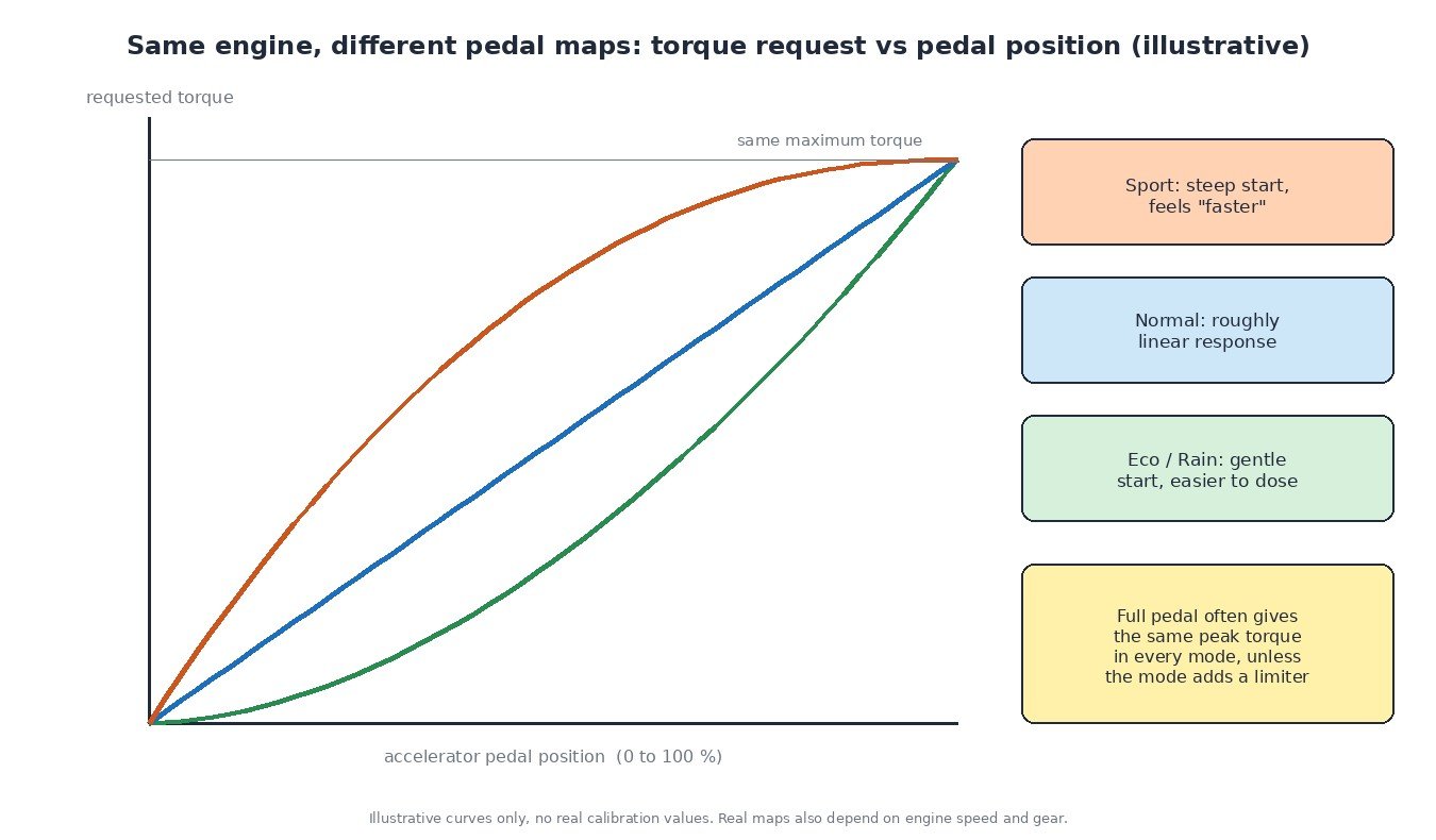
On modern torque-based engine management, the accelerator pedal does not open the throttle directly. The ECU converts pedal position and engine speed into a driver torque request, then the torque model decides how to deliver it with air, fuel and ignition. A Sport pedal map requests more torque early in the pedal travel, while an Eco or Rain map requests less, so the same foot movement produces a different response.
The important point for technicians is that full pedal often gives the same maximum torque in every mode. The car feels faster in Sport because the torque arrives earlier in the pedal travel, not because there is more of it. Some modes do add real limiters, such as reduced peak torque in a motorcycle Rain mode or a lower torque ceiling in a truck economy setting, so always check which maps are actually different. Pedal signals themselves come from the dual-track sensor described in our article on the accelerator pedal position sensor.
Modes across vehicle types
Cars
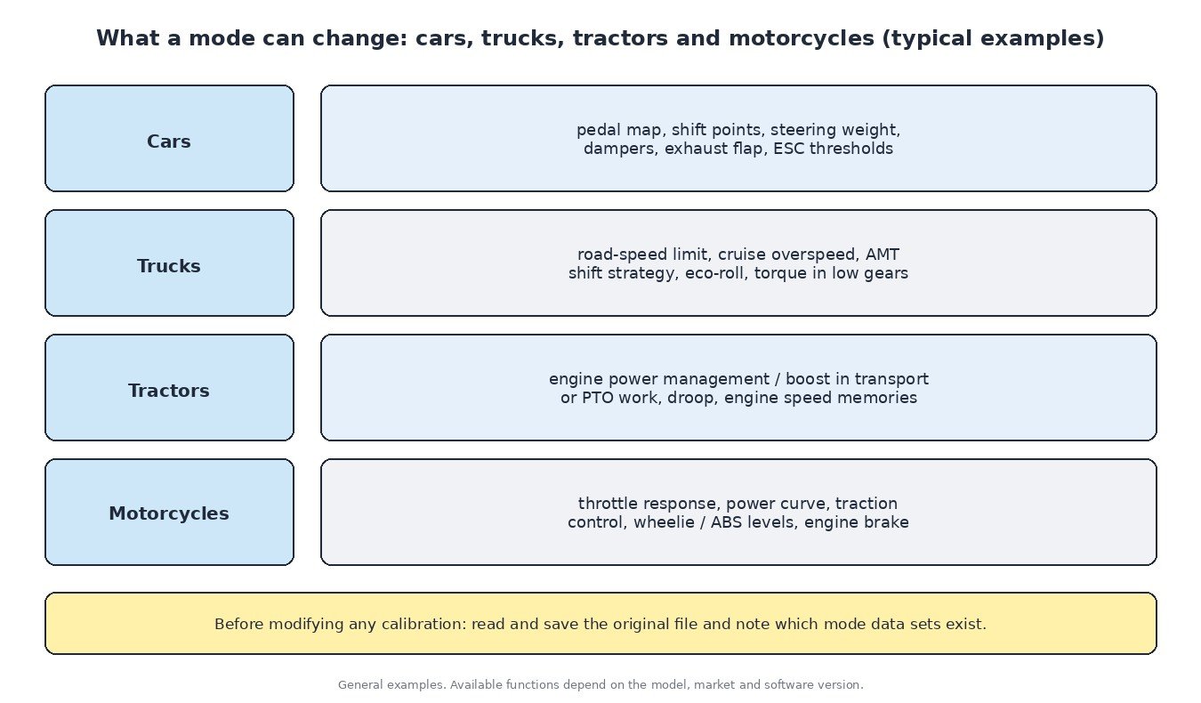
Typical car modes adjust pedal progression, shift strategy of the automatic gearbox, steering weight, adaptive dampers, exhaust flaps and the intervention thresholds of stability control. Eco modes may also enable coasting and reduce climate control load.
Trucks
Truck fleets use modes and parameter settings to manage fuel consumption: road-speed limit, cruise control overspeed, eco-roll (coasting in neutral), and the shift strategy of the automated manual transmission. Many of these values are customer parameters set by the dealer rather than switchable by the driver.
Tractors and agricultural machines
Tractors often use engine power management: the engine can deliver extra power when the load and operating conditions allow it, for example during transport or PTO work, and the standard power curve the rest of the time. Operators can also store engine speed memories and choose droop behaviour for the governor, which changes how far engine speed falls under load.
Motorcycles
Riding modes usually combine throttle response, power delivery, traction control level, wheelie control, ABS settings and engine braking. Unlike many cars, motorcycle modes more often change the actual power output in the lower modes.
Multi-map and switchable calibrations in tuning
When a file is modified, every mode data set has to be considered. If only the Normal pedal map and torque limits are changed, the vehicle may behave differently in Sport or Eco. A clean calibration keeps the character of each mode consistent and keeps the protection maps sensible across all of them.
Some ECUs and tuning solutions also support switchable maps chosen by the driver, for example a standard and an increased map. Whether this is possible depends on the ECU, the software version and the tool, so it must be checked case by case. Identify the exact hardware and software version first, read and save the original file, and remember that the TCU often needs matching changes when engine torque goes up.
Diagnosing mode problems
- Mode will not change: check the switch input in the live data of the reading module, then whether the message reaches the other units.
- Mode resets or drops back: look for network faults, low supply voltage or an implausible-signal fault in one module.
- One system ignores the mode: wrong coding or software level after module replacement is a common cause.
- Poor response in all modes: suspect a pedal, throttle or engine fault rather than the mode system itself.
Related fault codes (DTCs)
Mode systems rarely have their own generic codes. Faults usually appear as network, pedal, throttle or control module codes such as these. Manufacturers also use their own specific codes.
| Code | Meaning | Typical causes |
|---|---|---|
| U0100 | Lost communication with ECM/PCM “A” | CAN wiring or connector fault, engine ECU without power or ground, failed module, terminating resistor problem |
| U0101 | Lost communication with TCM | Gearbox control unit not powered, CAN wiring damage, water in connectors, failed TCU |
| U0140 | Lost communication with body control module | BCM supply or ground fault, CAN wiring problem, BCM failure or incorrect software |
| U0155 | Lost communication with instrument panel cluster (IPC) control module | Cluster supply or ground fault, network wiring damage, failed or wrongly coded cluster |
| P0700 | Transmission control system (MIL request) | The TCU has stored its own fault; read the transmission module for the detailed code |
| P2135 | Throttle/pedal position sensor/switch “A”/”B” voltage correlation | Worn throttle body or pedal sensor tracks, wiring resistance, poor 5 V reference or ground |
| P2138 | Throttle/pedal position sensor/switch “D”/”E” voltage correlation | Faulty accelerator pedal sensor, corroded pedal connector, damaged wiring or reference circuit |
| P2101 | Throttle actuator control motor circuit range/performance | Dirty or sticking throttle body, motor or wiring fault, low supply voltage, failed throttle body |
| P0601 | Internal control module memory checksum error | Corrupted or interrupted flash, incompatible or incorrectly prepared software, internal module fault |
| P0605 | Internal control module read only memory (ROM) error | Flash memory problem, failed programming session, internal ECU fault |
| P0606 | Control module processor | Internal ECU fault, supply voltage or ground problems, monitoring processor detecting an implausible result |
Generic SAE meanings shown. Check manufacturer data for exact definitions and test procedures.
Need a calibration that respects every drive mode? Upload your original ECU read to ECUFileMarket and get a file prepared for your exact software version.