
A dual-clutch transmission (DCT) shifts in a fraction of a second without interrupting drive, yet inside it is basically two manual gearboxes sharing one housing. Makers badge it DSG, PDK, Powershift or simply DCT. What makes it work is the transmission control unit (TCU) handing torque from one clutch to the other at exactly the right moment. Here is how the hardware and control logic work, and why calibration matters once engine torque rises.
Two gearboxes in one housing
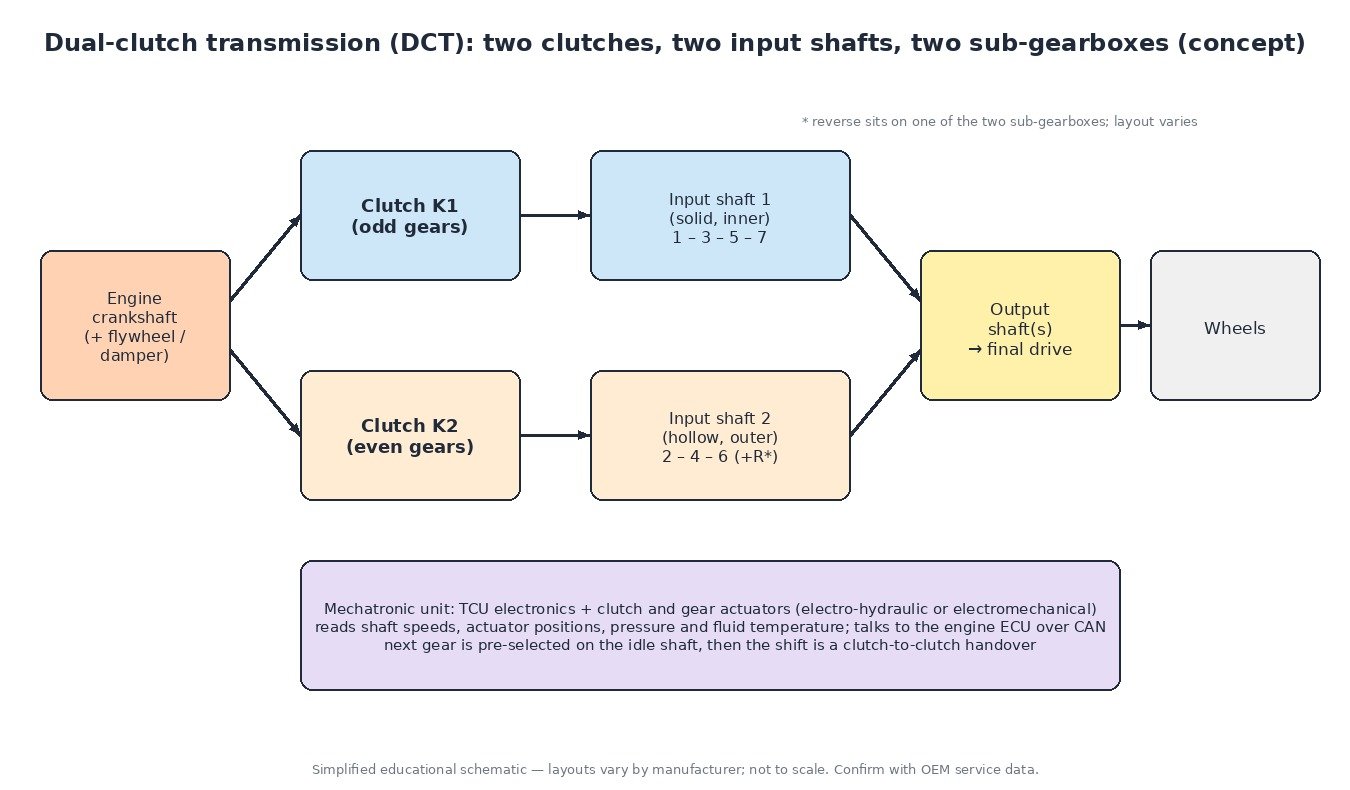
A DCT splits the gears into two groups. One clutch drives the odd gears (1, 3, 5 and 7 on a seven-speed). The other drives the even gears (2, 4, 6), and reverse sits on one of the two halves, depending on the design. To make this fit, the two input shafts are concentric: a solid inner shaft runs inside a hollow outer one, and each is connected to its own clutch.
Because the two halves are independent, the TCU can engage the next gear in advance on the shaft that isn’t carrying torque. The shift itself is then just one clutch releasing while the other applies.
Dry and wet clutches
- Dry clutches work like a manual gearbox clutch, without oil. They are compact and efficient and are common on lower-torque transverse units. Their weak point is heat from slipping in traffic, on hills and during repeated launches.
- Wet clutches are multi-plate packs running in transmission fluid, which carries heat away. They handle higher torque but need regular fluid and filter service.
The mechatronic unit
Most DCTs combine the TCU electronics with the actuators in one mechatronic unit mounted on or inside the gearbox. Depending on the design, it contains:
- an electro-hydraulic valve body with pressure-control and flow-control solenoids, fed by a mechanical or electric pump (some dry-clutch units use an electric pump with a pressure accumulator), or electromechanical motors on some designs;
- clutch actuators and gear actuators that move the shift forks;
- speed sensors for each input shaft and the output, travel sensors for the gear actuators, pressure sensors and a fluid temperature sensor.
The TCU constantly exchanges data with the engine ECU over CAN: actual and requested engine torque, rpm, pedal position, and torque-reduction requests during shifts.
How a shift is controlled
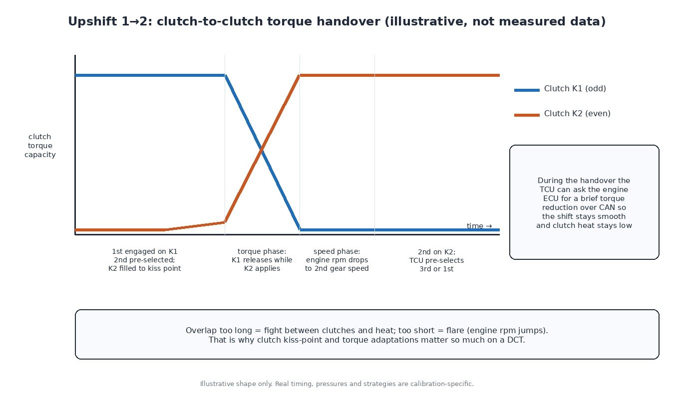
An upshift has two phases. In the torque phase the TCU ramps the off-going clutch down while the on-coming clutch takes the load. In the speed (inertia) phase engine speed falls to match the new gear, often helped by a brief engine torque reduction requested from the ECU. If the overlap is too long, the clutches fight each other and generate heat. If it is too short, the engine flares, meaning the rpm jumps before the new gear holds.
For this to be smooth, the TCU must know each clutch’s kiss point (also called touch or bite point), where it just starts to transmit torque, plus a model of clutch torque versus pressure or actuator travel. It also models clutch temperature and protects the clutches by changing shift timing, reducing creep or limiting engine torque when they get hot.
Adaptation: why it matters
Clutches wear and fluid ages, so the TCU continuously adapts kiss points and torque characteristics. After a clutch replacement, mechatronic replacement, TCU software update or sometimes a battery disconnection, a basic setting / clutch adaptation routine is often required with a diagnostic tool. These routines have conditions, such as a fluid temperature range and stable voltage. Skipping adaptation is a common cause of judder, harsh engagement or “new” faults after a repair.
Diagnostics tips
Always read the TCU itself, because a P0700 in the engine ECU only says the TCU has a fault. Check battery voltage, TCU supply and grounds, and fluid level and condition on wet-clutch units, before suspecting the mechatronic unit. On a road test, compare clutch slip, clutch temperature and adapted kiss points between the odd and even sides. Many DCTs shut down one sub-gearbox after a fault, so a car that only drives in odd or even gears tells you which half to look at.
Cars, trucks, tractors and bikes
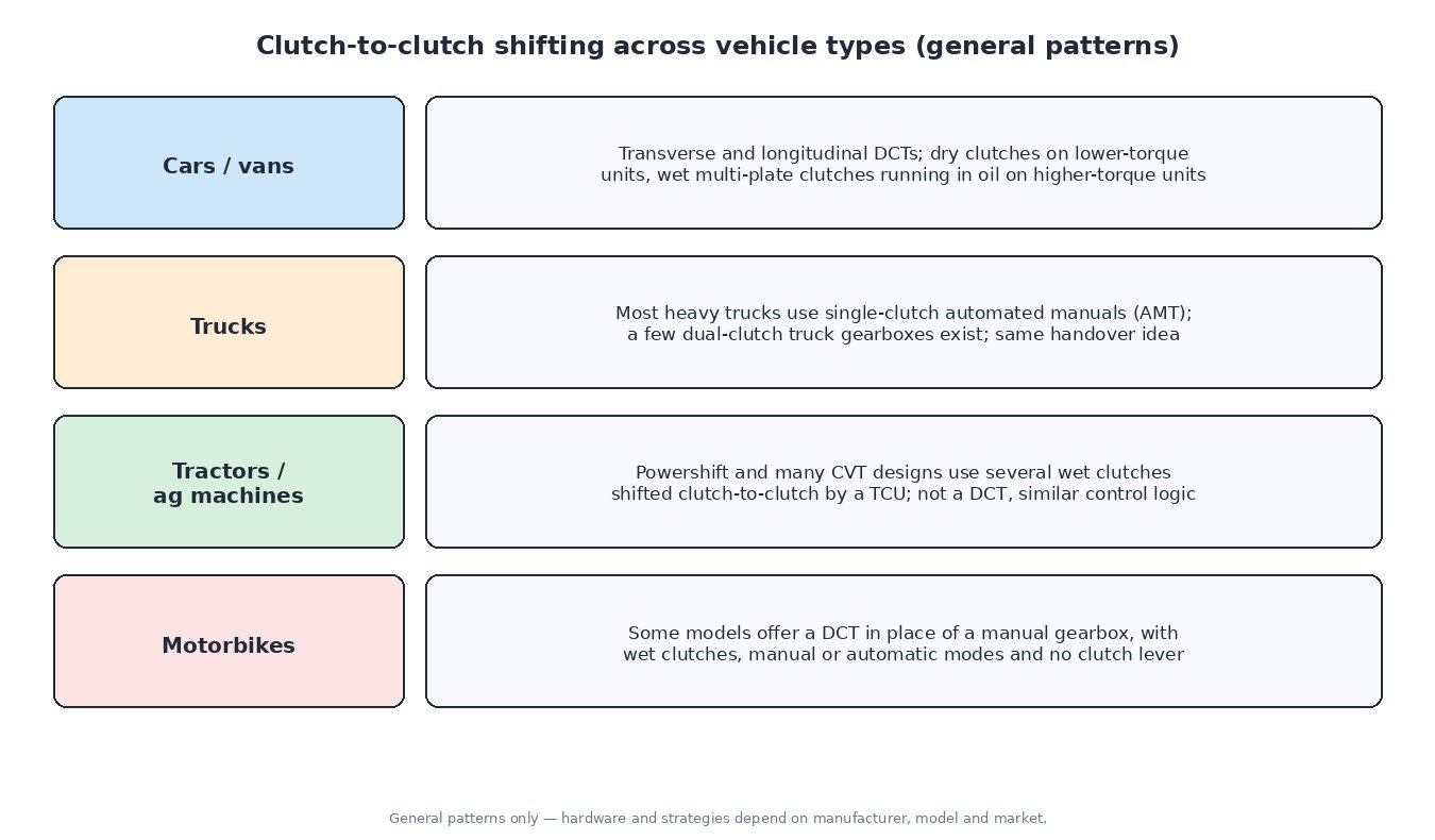
DCTs are most common in cars and vans. Most heavy trucks use single-clutch automated manuals, although dual-clutch truck gearboxes exist. Tractor powershift and many CVT transmissions shift several wet clutches clutch-to-clutch under TCU control, so the same ideas apply. Some motorbikes offer a DCT in place of a manual gearbox.
What this means for tuning
A DCT is calibrated around a maximum input torque. Raise engine torque with an engine-only remap, and the TCU may still limit it, the clutches may slip, or the clutch temperature model may react sooner. A proper DCT stage usually looks at the TCU too: torque limits, clutch pressure and clamping, shift timing and launch behaviour, always within what the hardware can safely hold. Check clutch condition and adaptation values before tuning. Back up the original TCU software first.
Related fault codes (DTCs)
Generic OBD-II codes (SAE J2012) often seen on DCTs. Manufacturers also store their own clutch and mechatronic codes; read them with an OEM-level tool.
| Code | Meaning | Typical causes |
|---|---|---|
| P0700 | Transmission Control System (MIL Request) | TCU has stored a fault; read the TCU for the real code |
| P0715 / P0716 / P0717 | Input/Turbine Speed Sensor “A” Circuit / Range/Performance / No Signal | Input shaft speed sensor or wiring fault, often inside the mechatronic unit; debris on the sensor |
| P0720 | Output Speed Sensor Circuit | Output speed sensor or wiring fault, damaged reluctor or target wheel |
| P0730 | Incorrect Gear Ratio | Clutch slip, gear actuator or shift fork fault, speed sensor error |
| P0731–P0735 / P0729 | Gear 1–5 Incorrect Ratio / Gear 6 Incorrect Ratio | Slipping clutch on that gear’s sub-gearbox, gear not fully engaged, worn synchroniser or selector |
| P0736 | Reverse Incorrect Ratio | Reverse gear engagement or clutch fault on the sub-gearbox carrying reverse |
| P0710–P0713 | Transmission Fluid Temperature Sensor “A” Circuit / Range/Performance / Low / High | Sensor or internal wiring fault, connector corrosion |
| P0218 | Transmission Fluid Over Temperature Condition | Long creeping or launching, towing, low fluid on wet units, cooler faults |
| P0805–P0808 | Clutch Position Sensor Circuit / Range/Performance / Low / High | Clutch travel sensor or wiring fault, actuator wear |
| P0810 | Clutch Position Control Error | Clutch actuator misses its target: pressure, actuator or adaptation fault |
| P0811 | Excessive Clutch “A” Slippage | Worn clutch, outdated kiss point, oil on a dry clutch, engine torque above clutch capacity |
| P0900–P0903 | Clutch Actuator Circuit/Open / Range/Performance / Low / High | Actuator, solenoid or valve wiring fault, mechatronic electrical fault |
| P0841 | Transmission Fluid Pressure Sensor/Switch “A” Circuit Range/Performance | Pressure sensor fault, hydraulic leak, pump or accumulator problem |
| P0868 | Transmission Fluid Pressure Low | Low fluid, pump wear, internal leakage, blocked filter |
| P0882 | TCM Power Input Signal Low | Weak battery, poor TCU supply or ground, corroded connector |
| P0562 | System Voltage Low | Battery or charging fault upsetting the actuators |
| P0613 | TCM Processor | Internal TCU fault, heat or water ingress, interrupted programming |
| U0100 | Lost Communication With ECM/PCM “A” | CAN wiring fault or engine ECU not responding; TCU loses torque data |
| U0101 | Lost Communication With TCM | TCU supply, ground, CAN wiring or internal TCU fault |
Closing
A DCT is two gearboxes and two clutches managed by software. Most of its smoothness, and most of its faults, come down to clutch control, adaptation and good communication with the engine ECU.
Need an engineered ECU or TCU file for a car, van, truck, tractor or bike? Upload your original read at ECUFileMarket.