
Before common rail took over, a big part of the medium-duty diesel world ran on a clever idea: use pressurised engine oil to drive the fuel injectors. That system is called HEUI, short for Hydraulically actuated Electronically controlled Unit Injector. It was developed by Caterpillar and used on Caterpillar and Navistar (International) engines from the 1990s and 2000s, including the Navistar-built Ford 7.3 and 6.0 Power Stroke diesels and mid-range engines such as the Caterpillar 3126, C7 and C9. Many of these engines are still working in pickups, delivery trucks, buses and off-highway machines. This guide explains how HEUI works, what the ECU controls, which faults are typical and what it means for diagnostics and calibration work.

The basic idea: oil does the pumping
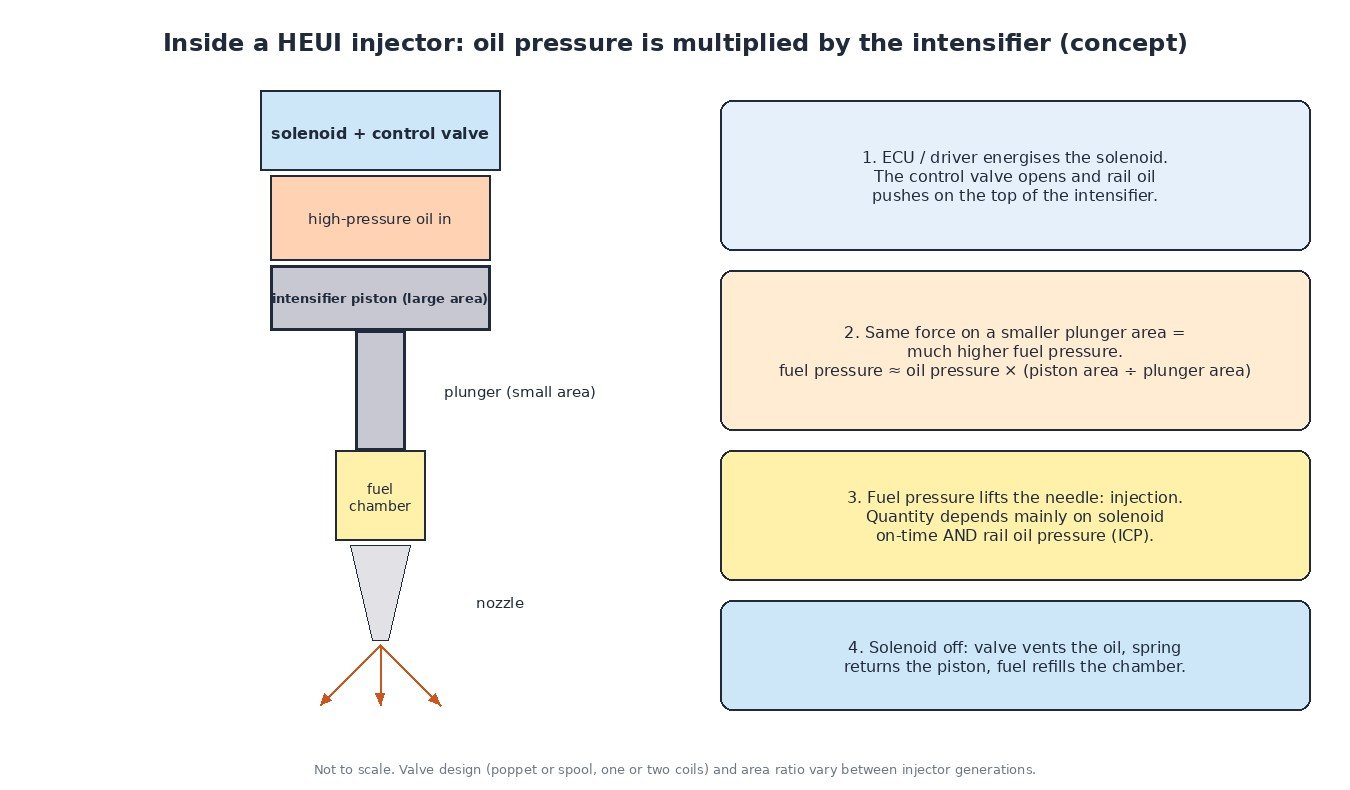
A conventional mechanical unit injector is pushed down by a camshaft lobe, so the injection pressure it can build is linked to engine speed and cam profile. HEUI removes the cam from the job. Instead, an engine-driven high-pressure oil pump takes lubricating oil from the engine and delivers it to an oil rail or gallery in the cylinder head. Every injector is connected to that rail. When the ECU decides it is time to inject, a solenoid in the injector opens a control valve and the high-pressure oil pushes down on a piston inside the injector.
The fuel side is separate. A low-pressure fuel supply (a lift pump and filters) keeps fuel galleries in the head full, and each injector draws its fuel from there. The fuel is only raised to injection pressure inside the injector itself, at the moment of injection.
Inside the injector: the intensifier
The key part is the intensifier piston. Rail oil acts on its large top surface, while its lower end is a much smaller plunger that pressurises the fuel. Because the force is the same on both ends, the fuel pressure is roughly the oil pressure multiplied by the ratio of the two areas. A moderate oil pressure in the rail therefore becomes a much higher fuel pressure at the nozzle. When the fuel pressure is high enough, the nozzle needle lifts and injection starts.
When the solenoid is switched off, the control valve closes the oil inlet and vents the oil above the piston. A return spring pushes the piston and plunger back up, the fuel chamber refills from the low-pressure supply, and the injector is ready for the next cycle. Early designs used a single solenoid with a poppet valve; later generations, such as the injectors on the Ford 6.0, use a spool valve with two coils, one to open and one to close. Some versions can also split the delivery into a pilot and a main injection.
What the ECU controls
Because injection pressure no longer depends on the cam, the ECU can set it freely. It does this with two parts:
- The injection pressure regulator (IPR) valve. A PWM-controlled valve on the pump or oil circuit that dumps excess oil back to the sump. A higher duty cycle restricts the dump path and raises rail pressure.
- The injection control pressure (ICP) sensor. A pressure sensor on the high-pressure oil circuit that reports the actual pressure. Some older engines also had a separate injection control pressure sensor fitted to the pump side.
The ECU looks up a desired ICP from engine speed and load, compares it with the sensor reading and adjusts IPR duty in a closed loop. This is the same principle as rail pressure control on common rail, except that the controlled fluid is oil, not fuel.
The amount of fuel delivered depends on two things: how long the solenoid is energised and how high the oil pressure is. The calibration therefore contains maps for desired ICP, injection timing and pulse width, together with corrections for oil temperature, engine temperature and barometric pressure. The injector solenoids need fast, strong current pulses, so many HEUI engines use a separate driver: an injector driver module (IDM) on the 7.3 and a fuel injection control module (FICM) on the 6.0, which raises the supply to around 48 V. On other engines the drivers sit inside the ECM.
Why oil condition matters so much
On a HEUI engine the oil is part of the injection system. That has a few consequences that catch technicians out:
- Viscosity. Thick, cold oil slows the injector’s internal movement, so cold starts can be rough or slow. Thin, fuel-diluted oil leaks past seals more easily.
- Aeration. Air bubbles in the oil make the actuating fluid compressible, which delays and weakens injection and causes misfire or power loss.
- Cleanliness and deposits. Dirty oil and varnish can make the injector control valve sticky, giving the typical rough cold idle that improves once warm.
- Leaks. Every seal, plug and fitting in the high-pressure oil circuit is a possible leak. An external leak shows as oil; an internal one only shows as low ICP or high IPR duty.
Correct oil grade, level and change intervals are not just maintenance on these engines; they are part of fuel system health. Our article on engine oil pressure sensing covers the separate lubrication side.
Diagnosing hard starts and low power
Many HEUI engines will not fire the injectors until a minimum injection control pressure is reached during cranking. So the classic HEUI no-start is an engine that cranks well, makes no smoke and simply never fires. A sensible order:
- Read codes in the ECU and the injector driver. Note pressure-related codes and driver supply voltage faults.
- Check the oil: level, grade, smell of fuel, signs of coolant or foaming.
- Log ICP and IPR duty while cranking and running. Low ICP with a high IPR duty cycle means the ECU is asking for pressure and not getting it: think leak, weak pump or leaking IPR valve.
- Check the ICP sensor plausibility with key on, engine off. A reading well above zero points to a sensor or circuit fault.
- Check driver supply voltage, injector circuits and the low-pressure fuel supply. Weak batteries or a failing driver module cause hard starts too. A voltage-drop test on feeds and grounds is quick and often revealing.
- Isolate high-pressure oil leaks with the manufacturer’s procedure (blocking parts of the circuit or an air test) before replacing the pump or injectors.
Contribution or balance tests in the scan tool and an oscilloscope on the injector current help to find a single weak injector.

Calibration and tuning notes
A HEUI calibration has more interacting maps than many people expect. Raising pulse width without considering desired ICP, timing and smoke limits gives poor results, and higher pressure targets put more load on the oil pump, seals and injectors. Before any file work, the engine must start and idle properly with ICP following its target, the injector driver supply must be healthy, and the oil system must be leak free. Save a full original read first and log ICP, IPR duty and pulse width after the change. Keep the original protections and limiters in place; our guide to ECU limiters explains why.
Related fault codes (DTCs)
| Code | Meaning | Typical causes |
|---|---|---|
| P2283 | Injector Control Pressure Sensor Circuit | ICP sensor fault, damaged connector or wiring, oil in the sensor connector, 5 V reference problem |
| P2284 | Injector Control Pressure Sensor Circuit Range/Performance | Skewed or sluggish ICP sensor, reading implausible against desired pressure or engine-off value |
| P2285 | Injector Control Pressure Sensor Circuit Low | Signal shorted to ground, open 5 V reference, failed sensor |
| P2286 | Injector Control Pressure Sensor Circuit High | Signal shorted to voltage, open ground, failed sensor |
| P2287 | Injector Control Pressure Sensor Circuit Intermittent | Loose or corroded connector, chafed harness, intermittent sensor |
| P2288 | Injector Control Pressure Too High | IPR valve sticking closed or not dumping oil, IPR circuit fault, faulty ICP reading |
| P2289 | Injector Control Pressure Too High – Engine Off | ICP sensor offset or failure (pressure should be near zero with the engine off), circuit fault |
| P2290 | Injector Control Pressure Too Low | High-pressure oil leak, worn or weak high-pressure oil pump, IPR valve leaking or contaminated, low or aerated oil |
| P2291 | Injector Control Pressure Too Low – Engine Cranking | High-pressure oil leak, weak pump, low oil level, IPR valve fault; typical hard-start or no-start code |
| P2623 | Injector Control Pressure Regulator Circuit/Open | IPR valve coil open, damaged connector or wiring, driver fault |
| P0611 | Fuel Injector Control Module Performance | Injector driver module internal fault, low supply voltage to the module, poor grounds, weak batteries |
| P0201-P0208 | Injector Circuit/Open – Cylinder 1 to 8 | Injector solenoid open circuit, harness or under-valve-cover connector fault, driver output fault |
| P0300 | Random/Multiple Cylinder Misfire Detected | Low injection control pressure, sticking injectors (oil quality), fuel supply or aeration problems, low compression |
Code wording follows the generic SAE J2012 definitions; some engines and model years also use manufacturer-specific codes, and heavy-duty versions report faults as J1939 SPN/FMI. Always confirm with the service information for the exact engine.
Need an original or modified ECU file for a HEUI engine, a common-rail diesel or any other ECU? Order it from the file service at ECUFileMarket.