
Listen to an old indirect-injection diesel and then to a modern common-rail engine at idle. The difference in noise is mostly down to one idea: the modern engine does not inject its fuel in one shot. It splits each combustion cycle into several precisely timed injection events, usually called pilot, main and post injections. This guide explains what each event does, how the ECU calculates them, what changes when an injector or the calibration is wrong, and which fault codes are typically involved.

Why one injection is not enough
In a diesel engine, fuel ignites by itself after it is sprayed into hot compressed air. There is always a short ignition delay between the start of injection and the start of combustion. With a single large injection, a lot of fuel collects during this delay and then burns almost at once. The pressure in the cylinder rises very quickly, which causes the typical diesel knock, higher mechanical stress and more NOx.
Older mechanical pumps and early electronic pumps could only shape this partly. Common rail separates pressure generation from injection timing: the rail is held at a high pressure all the time and the ECU opens each injector electrically whenever it wants. That makes several short events per cycle possible. Piezo injectors and fast solenoid injectors can open and close quickly enough to place events close to each other. How many events an engine uses depends on the system generation and the calibration. See our guide to common-rail injectors for the hardware side.
The injection events, one by one
Pilot injection(s)
One or more very small injections before the main event. The pilot fuel starts burning first and pre-heats the charge. As a result, the main injection ignites with a much shorter delay and burns more smoothly. Benefits: lower combustion noise, smoother idle and better cold starting. The cost is a small penalty in soot or fuel consumption at some operating points, so pilots are usually reduced or switched off at high load and speed.
Main injection
The main injection delivers most of the fuel and produces the torque. Its start of injection (SOI) is one of the most important calibration values. Earlier injection usually improves efficiency but raises peak pressure and NOx. Later injection lowers NOx and combustion temperature but raises exhaust temperature, soot and fuel consumption.
After injection (close post injection)
A short injection right after the main, while the flame is still burning. It adds turbulence and heat late in combustion and helps burn off soot formed during the main event. It still contributes a little to torque.
Late post injection
A late post injection is placed so far after top dead centre that the fuel does not burn usefully in the cylinder. The unburnt fuel goes into the exhaust and reacts in the diesel oxidation catalyst, which raises exhaust temperature. This is the main tool for active DPF regeneration and for warming up the aftertreatment. A known side effect is oil dilution: some of the late fuel wets the cylinder walls and ends up in the sump. This is why many short trips with interrupted regenerations can raise the oil level. Some designs use a separate exhaust fuel injector instead of in-cylinder late post injection.
How the ECU calculates the pattern
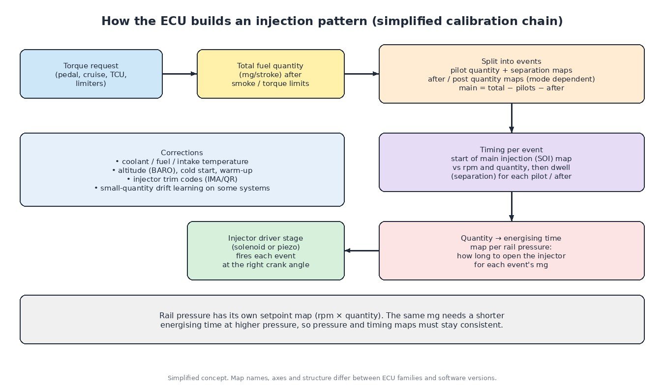
The injection pattern sits at the end of the torque model. In simplified form:
- Torque request from the pedal, cruise control, gearbox or traction control.
- Total fuel quantity (usually in mg per stroke), limited by smoke, torque and protection limiters.
- Split into events. Maps decide pilot quantities, how many pilots are active, and after/post quantities, usually as a function of engine speed, quantity and temperature. Different maps are often used for different operating modes, such as normal driving, warm-up or regeneration.
- Timing. A start-of-injection map sets the main event. Separation (dwell) maps place the pilot and after events relative to it.
- Quantity to energising time. For each event, the requested quantity is converted into how long the injector is driven. This depends on rail pressure: the same quantity needs a shorter opening at higher pressure.
Corrections are applied along the way. Typical examples are coolant, fuel and intake air temperature, altitude, cold start and warm-up. Injector trim codes (IMA/QR/C2I, depending on the maker) compensate for production tolerances of each injector. Some systems also learn small-quantity drift over the injector’s life, for example with a deliberate tiny test injection during overrun. Small pilot quantities are very sensitive to injector wear, so this learning matters for noise and smoothness.
Diagnostics: symptoms and where to look
- Increased knock or rattle, especially cold or at idle: drifting pilot quantity, an injector leaking or sticking, a wrong trim code after injector replacement, or low compression. Also check that glow plugs work, see our glow plug guide.
- Rough idle: compare cylinder balance or smooth-running correction values in live data. One cylinder far from the others points to that injector or to compression on that cylinder. A leak-off (return flow) test helps to confirm.
- Smoke and low power: check the air side first (boost, MAF, leaks), then rail pressure actual versus setpoint, then injectors. Many injector complaints are really air-path faults.
- Rising oil level: look at regeneration history and driving pattern before blaming an injector.
A lab scope with a current clamp on an injector line lets you actually see how many events are fired per cycle and how the pattern changes with load and temperature.

Tuning and calibration notes
Performance calibrations on common-rail diesels usually work on total quantity, rail pressure, SOI and the related limiters, not by deleting events. The pattern maps are tied together: changing rail pressure changes the energising time needed for every event, including the tiny pilot quantities. Unbalanced changes can bring back combustion noise or raise exhaust temperatures. Post-injection and regeneration logic belong to the emissions system and should stay working as designed.
The calibration lives in the ECU flash, so always start from a full, verified original read. See our article on ECU reading methods.
Related fault codes (DTCs)
These are generic SAE definitions. Manufacturers also use their own codes for injector quantity deviation, trim code errors and learning limits, so always check the definition for the specific vehicle.
| Code | Meaning | Typical causes |
|---|---|---|
| P0087 | Fuel Rail/System Pressure Too Low | Clogged fuel filter, weak lift pump, air in fuel, worn high-pressure pump, injectors leaking back too much, faulty pressure regulator or metering valve |
| P0088 | Fuel Rail/System Pressure Too High | Sticking pressure control valve or metering valve, wiring fault, faulty rail pressure sensor |
| P0093 | Fuel System Leak Detected – Large Leak | External high-pressure leak, injector stuck open or heavy internal leak, cracked line or rail fitting |
| P0180 | Fuel Temperature Sensor “A” Circuit | Faulty fuel temperature sensor, connector or wiring; the ECU uses fuel temperature for quantity correction |
| P0201 | Injector Circuit/Open – Cylinder 1 | Open injector coil or piezo stack, damaged wiring or connector, ECU driver fault (P0202–P0204 etc. for other cylinders) |
| P0216 | Injector/Injection Timing Control Circuit | Timing control actuator or circuit fault; meaning depends on the system, check OEM definition |
| P0263 | Cylinder 1 Contribution/Balance | Injector delivering too much or too little, low compression on that cylinder, wrong trim code (P0266, P0269… for other cylinders) |
| P0300 | Random/Multiple Cylinder Misfire Detected | Injector faults, air in fuel, low compression, low rail pressure |
| P2146 | Fuel Injector Group “A” Supply Voltage Circuit/Open | Wiring or connector fault on the injector bank supply, shorted injector, ECU output stage fault |
Want more from your common-rail diesel? Upload your original ECU read at ecufilemarket.com and get a custom tuning file prepared for your vehicle.