
A diesel has no spark plug. It relies on the heat of compression to ignite the fuel, and on a cold morning that heat is not always enough. Cold cylinder walls and pistons soak heat out of the compressed air, cranking is slow and the fuel atomises poorly. The answer is a cold-start aid, usually a glow plug in every cylinder, managed by the ECU and a glow control unit. This guide explains how glow plugs and preheat systems work, how the ECU decides when and how long to glow, and how to diagnose them on cars, trucks and agricultural machines.
Why diesels need preheating
Ignition in a diesel depends on the compressed charge reaching the fuel’s autoignition temperature. When the engine is cold, much of the compression heat is lost to the metal around it, so the charge ends up cooler. Modern diesels also use lower compression ratios than older designs to reduce NOx and friction, which leaves less margin at cold start. A glow plug adds a hot surface right where the spray arrives, so the first injections ignite reliably. The result is faster starting, less white smoke, a smoother cold idle and lower hydrocarbon emissions in the first minutes.
Glow plug types
- Metal sheathed, self-regulating: a heating coil plus a regulating coil inside a steel sheath, packed with magnesium oxide powder. As the regulating coil heats up its resistance rises and the current falls, so the plug limits itself. These run on full battery voltage, usually through a simple relay.
- Low-voltage, fast-heating metal plugs: designed for a lower nominal voltage and driven by an electronic glow control unit with PWM, which lets them reach working temperature within a few seconds and hold it accurately.
- Ceramic glow plugs: a silicon nitride heating element that tolerates higher temperatures and long post-glow periods. They are durable in service but brittle if dropped or overtightened.
- Pressure-sensing glow plugs: some engines use plugs with an integrated combustion pressure sensor, giving the ECU feedback for combustion control.
The glow control unit (GCU)
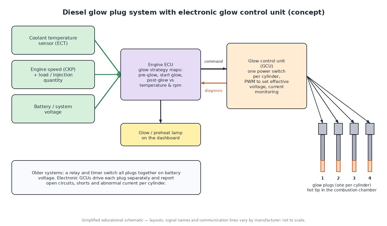
On current diesels the ECU does not drive the plugs directly. It sends a command to a glow control unit, which contains a power switch for each cylinder. The GCU uses pulse-width modulation to produce the effective voltage the ECU requests, compensating for battery voltage so the plug temperature stays on target whether the battery is fresh or weak. It also monitors the current in each channel and reports open circuits, shorts and abnormal current back to the ECU, which is how per-cylinder codes are set. Older systems used a relay and a timer that switched all plugs together, with little or no diagnosis.
Pre-glow, start glow and post-glow
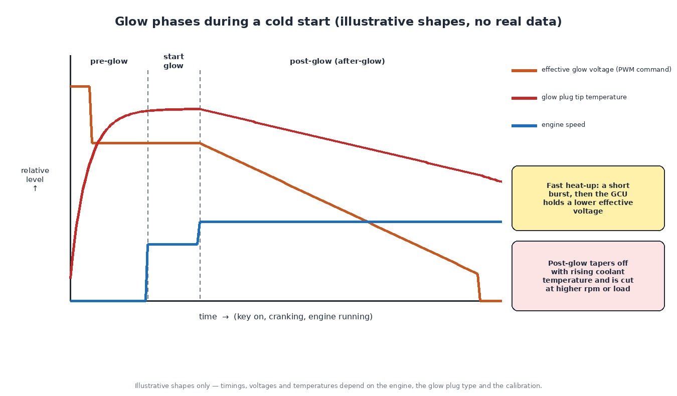
- Pre-glow: at key-on the ECU reads coolant temperature and switches on the preheat lamp. The colder the engine, the longer the pre-glow; with a warm engine it may be skipped.
- Start glow: the plugs stay on during cranking, when the starter motor pulls the battery voltage down.
- Post-glow (after-glow): after the engine fires, glowing continues for a period that depends on coolant temperature. It stabilises combustion and reduces smoke, noise and emissions. It is reduced or cancelled at higher rpm and load, and some engines also use an intermediate glow phase to support exhaust aftertreatment, such as during DPF regeneration.
Trucks, tractors and small diesels
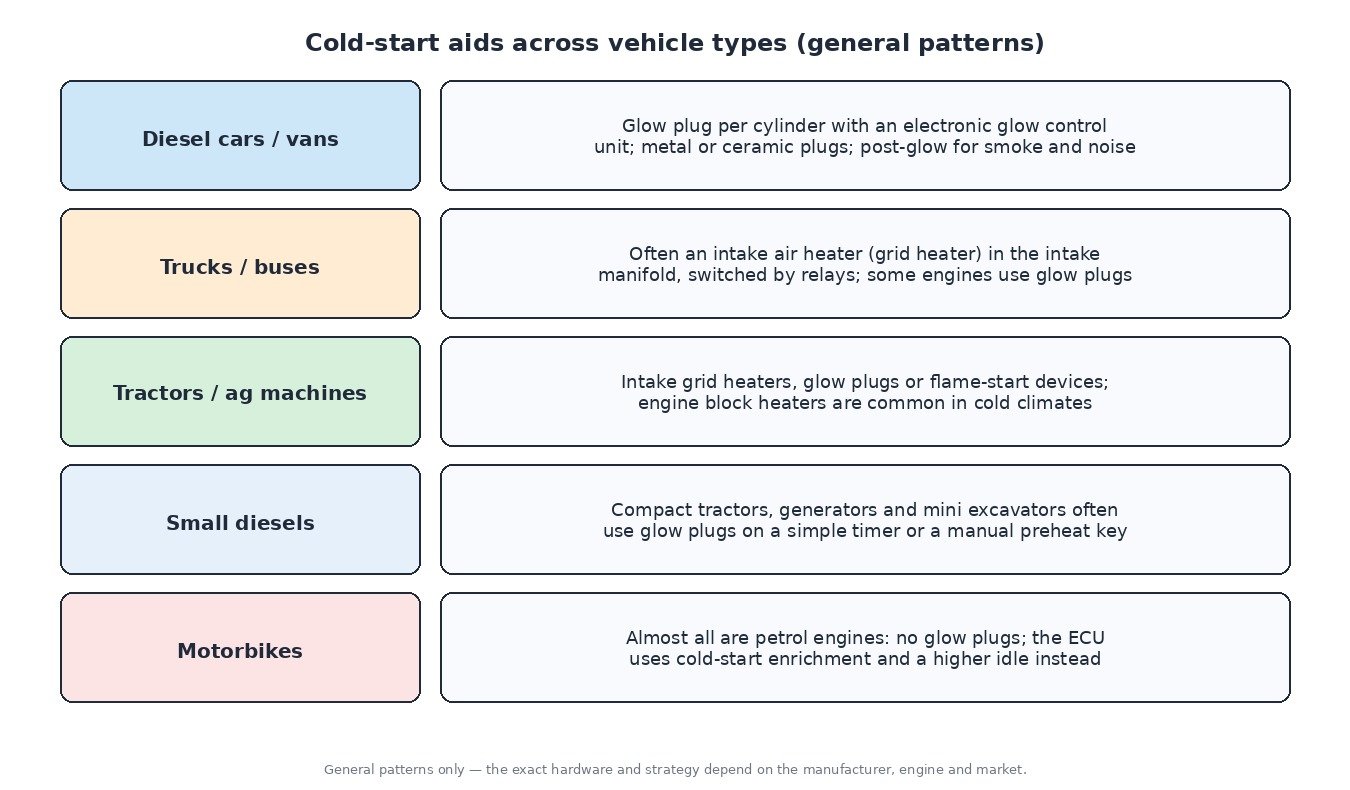
Many heavy-duty truck and agricultural engines use an intake air heater instead of, or alongside, glow plugs. It is an electric grid element in the intake manifold that warms the incoming air. It draws a high current and is switched by one or two heavy relays commanded by the ECU, which also controls pre-heat and post-heat time. Some tractors use a flame-start device that burns a small amount of fuel in the intake, and engine block heaters are common in cold climates. Compact tractors, generators and mini excavators often have glow plugs on a simple timer or a manual preheat key position. Motorbikes are almost all petrol, so instead of preheating the ECU uses cold-start enrichment and a raised idle.
Diagnosing glow and cold-start faults
- Read codes and live data first: check coolant temperature against ambient on a cold engine. An ECT sensor reading too warm shortens preheat and causes hard cold starts with no glow code at all.
- Test each plug: measure resistance or, better, current draw per cylinder with a clamp meter, and compare cylinders against each other and the manufacturer’s specification. An open plug is a clear failure. Never bench-test low-voltage plugs directly on 12 V.
- Check supply and grounds: the GCU or relay feed, main fuse, earth points and the command line from the ECU.
- Remove plugs with care: on high-mileage engines plugs can seize and snap. Work on a warm engine, use penetrating oil, the correct tool and the specified torque, and use an extraction kit if one breaks.
- Look beyond the glow system: battery condition and cranking speed, low rail pressure, injector back-leak, air in the fuel and low compression all cause hard starting too.
Related fault codes (DTCs)
Generic OBD-II codes per SAE J2012. Manufacturers word some codes differently and may add their own codes for glow plug and GCU faults.
| Code | Meaning | Typical causes |
|---|---|---|
| P0380 | Glow Plug/Heater Circuit “A” | Failed glow plug or glow relay/GCU, blown fuse, open or corroded supply wiring |
| P0381 | Glow Plug/Heater Indicator Circuit | Fault in the preheat lamp circuit or instrument cluster driver |
| P0382 | Glow Plug/Heater Circuit “B” | Second glow circuit or relay bank open or shorted, failed plug on that bank |
| P0383 | Glow Plug Control Module Control Circuit Low | Command line between ECU and GCU shorted to ground, faulty GCU |
| P0384 | Glow Plug Control Module Control Circuit High | Command line shorted to voltage or open, faulty GCU or connector |
| P0670 | Glow Plug Control Module Control Circuit | Open or poor connection in the ECU-to-GCU control circuit, GCU without power or ground |
| P0671 | Cylinder 1 Glow Plug Circuit | Burnt-out plug, broken terminal nut or bus bar, damaged harness to cylinder 1 |
| P0672 | Cylinder 2 Glow Plug Circuit | As P0671, for cylinder 2 |
| P0673 | Cylinder 3 Glow Plug Circuit | As P0671, for cylinder 3 |
| P0674 | Cylinder 4 Glow Plug Circuit | As P0671, for cylinder 4 |
| P0675 | Cylinder 5 Glow Plug Circuit | As P0671, for cylinder 5 |
| P0676 | Cylinder 6 Glow Plug Circuit | As P0671, for cylinder 6 |
| P0677–P0682 | Cylinder 7–12 Glow Plug Circuit | As P0671, for cylinders 7 to 12 on larger engines |
| P0683 | Glow Plug Control Module to PCM Communication Circuit | Open or shorted diagnostic/communication line, GCU fault |
| P0684 | Glow Plug Control Module to PCM Communication Circuit Range/Performance | Intermittent connection, corrupted signal, incompatible or faulty GCU |
| P0540 | Intake Air Heater “A” Circuit | Grid heater, heater relay or high-current cable fault (common on trucks and tractors) |
| P0541 | Intake Air Heater “A” Circuit Low | Relay control or heater circuit shorted to ground |
| P0542 | Intake Air Heater “A” Circuit High | Relay stuck closed or circuit shorted to voltage |
| P0543 | Intake Air Heater “A” Circuit Open | Burnt heater element, loose or corroded main terminal, open relay |
| P0117 | Engine Coolant Temperature Sensor 1 Circuit Low | Sensor or wiring shorted to ground; the ECU sees a very hot engine and may shorten preheat |
| P0118 | Engine Coolant Temperature Sensor 1 Circuit High | Open circuit or failed sensor; the ECU sees a very cold engine and uses substitute values |
| P0562 | System Voltage Low | Weak battery, charging fault, poor grounds; glow and cranking performance suffer |
| P0335 | Crankshaft Position Sensor “A” Circuit | No rpm signal: cranks but no start, independent of the glow system |
| P0087 | Fuel Rail/System Pressure – Too Low | Low-pressure supply, filter, pump or injector leakage; a common cause of hard starting that is mistaken for glow faults |
What it means for tuning
Glow strategy maps, start injection quantities and cold-start timing live in the ECU calibration. An engineered tuning file normally leaves the preheat strategy alone and keeps start and warm-up behaviour at the manufacturer’s level, because a richer start quantity brings smoke and extra wear without any gain. The glow system must also be fault-free before a car is judged on a new file: a dead plug causes rough cold running that has nothing to do with the calibration. Checksum correction, where required, is available on ECUFileMarket as a separate paid option.
Need an engineered tuning file for a diesel car, truck or tractor? Upload your original ECU read at ECUFileMarket.