
A warm engine is easy to run: fuel evaporates well, oil flows freely, clearances are where the designers wanted them and the lambda sensor is already controlling the mixture. A cold engine is a different machine. Fuel condenses on cold port and cylinder walls, friction is higher, the catalyst does nothing yet and the lambda sensor cannot be trusted until it is hot. The ECU spends the first minutes after every cold start running a separate set of strategies to deal with this. Knowing how those strategies work makes cold-start complaints much easier to diagnose.

Why a cold engine needs special treatment
On a petrol engine only the fuel that is vaporised takes part in combustion. When the intake ports and cylinder walls are cold, a large share of the injected fuel lands on them as a liquid film and either evaporates late or leaves as unburned hydrocarbons. To get a combustible mixture at the spark plug, the ECU has to inject noticeably more fuel than the airflow alone would suggest. Direct-injection petrol engines reduce wall wetting in the port but still need adapted injection timing and sometimes several injections per cycle while cold.
A diesel has a different problem. It relies on compression heat to ignite the fuel, and a cold block and cylinder head pull heat out of the compressed air. Ignition delay grows, combustion becomes noisy and incomplete, and the engine produces white smoke until temperatures rise. That is why diesels use glow plugs or intake air heaters, and why their start calibrations treat rail pressure and injection timing so carefully.
On both types, higher oil viscosity means more friction, so the engine needs more air and fuel just to idle, and the battery has to deliver more current to crank it.
Phase 1: cranking
During cranking the ECU has little reliable airflow information, so most petrol calibrations use a dedicated start fuel quantity looked up mainly from coolant temperature, often corrected for cranking speed and the number of revolutions since cranking began. The ECU first needs crank and cam synchronisation before it can inject sequentially.
On a common-rail diesel the ECU must first build a minimum rail pressure before it releases injection, and it may use pilot injections and adapted timing to keep ignition delay under control. The glow system is usually active before and during cranking, with duration based on coolant temperature and battery voltage. Larger truck and tractor engines often use an intake grid heater instead of, or in addition to, glow plugs. For details see our guides to how glow plugs and glow control work and the diesel intake air heater.
Phase 2: after-start enrichment
Once the engine fires, the fuel film on the walls is still building up, so the ECU adds an after-start enrichment on top of the normal warm-up correction. This extra fuel decays over a calibrated number of revolutions or seconds. At the same time the idle speed target is raised. The higher idle helps the engine overcome friction, keeps it from stalling when the alternator and heater blower load it, and adds heat to the exhaust.

Phase 3: warm-up and catalyst heating
During warm-up the enrichment and the idle target fall step by step, mostly as a function of coolant temperature. Petrol engines with a three-way catalyst add a catalyst heating strategy: the ignition is retarded well after the usual point so more of the combustion energy leaves as exhaust heat, while the throttle opens further to keep the idle speed. This brings the catalyst to light-off quickly, which matters because most of a modern car’s tailpipe emissions are produced in the first minute or two after a cold start. Some engines also run secondary air injection during this phase. You can read more about light-off in our article on how a catalytic converter works.
Calibrations also commonly limit the engine while cold: a lower rev or torque limit, later upshifts on automatic gearboxes, delayed EGR, a closed or map-controlled thermostat, and some diagnostic monitors held back until the engine reaches operating temperature.
Phase 4: closed loop
The lambda sensor only gives a useful signal when its ceramic element is hot, so the ECU powers its heater as soon as it is safe (it may wait until condensation in the exhaust has had time to clear to avoid cracking the element). When the sensor is ready and the engine has passed a minimum coolant temperature, the ECU switches to closed-loop fuel control and the fuel trims start correcting the mixture. From here on the cold-start corrections fade out and the normal maps take over.
Why the coolant sensor matters so much
Almost every cold-start table is indexed by coolant temperature. If the ECT sensor reads too warm, the engine gets too little fuel and idle on a cold morning and starts badly or stalls. If it reads too cold, the engine runs rich, smells of fuel, uses more of it and may fail an emissions test, while the cooling fan and closed-loop control may behave strangely. A thermostat stuck open has a similar effect: the engine never reaches operating temperature, so it stays in warm-up mode and often stores P0128. Our ECT sensor deep dive covers the circuit and measurements.
Practical diagnosis
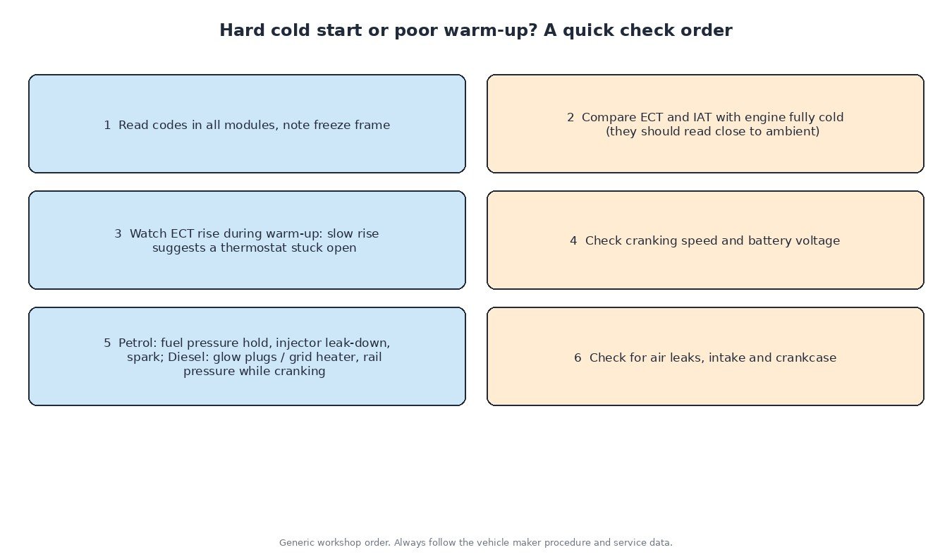
- Cold-soak check: after the vehicle has stood overnight, ECT and IAT in live data should read close to each other and to the ambient temperature. A large gap points to a faulty sensor or wiring.
- Warm-up curve: log coolant temperature from a cold start. A slow, stalled rise usually means the thermostat is open too early.
- Cranking: check cranking speed and battery voltage. Slow cranking lowers compression heat on a diesel and can drop the ECU supply on any engine.
- Petrol fuel: a fuel pump check valve or injector that leaks down overnight causes long cranking only after the car has stood.
- Diesel: test glow plugs or the grid heater and watch actual versus desired rail pressure while cranking. In winter, check for waxed fuel and a blocked filter.
- Trucks, tractors and machines: 24 V systems with tired batteries, wrong-grade oil and diesel left standing over a season are the classic causes of cold-start trouble.
- Motorcycles: fuel-injected bikes use the same ideas with engine or oil temperature as the main input; older carburetted bikes use a choke or enrichment circuit instead.
What this means for tuning
A sensible remap leaves start, after-start and warm-up tables alone unless there is a specific reason to change them, and keeps cold-engine protection limits in place. If an engine starts badly only after a file was written, compare the start-related maps with the original read before suspecting hardware, and always keep a full original backup.
Related fault codes (DTCs)
These generic codes are often linked to cold starts, warm-up and the sensors the ECU relies on during that phase. Manufacturer-specific codes may add more detail.
| Code | Meaning | Typical causes |
|---|---|---|
| P0116 | Engine coolant temperature circuit range/performance | ECT sensor reading implausible against model or other sensors, sensor drifting, thermostat stuck open |
| P0117 | Engine coolant temperature circuit low | Sensor shorted, signal wire shorted to ground (reads very hot) |
| P0118 | Engine coolant temperature circuit high | Open circuit, unplugged or corroded connector, failed sensor (reads very cold) |
| P0111 | Intake air temperature sensor circuit range/performance | IAT sensor drift or implausible value versus coolant temperature after a cold soak |
| P0125 | Insufficient coolant temperature for closed loop fuel control | Thermostat stuck open, ECT sensor reading low, very cold ambient conditions |
| P0128 | Coolant thermostat (coolant temperature below thermostat regulating temperature) | Thermostat stuck open or opening early, ECT sensor fault, low coolant |
| P0030 | HO2S heater control circuit (bank 1 sensor 1) | Lambda sensor heater element open, wiring or fuse fault, heater driver fault |
| P0135 | O2 sensor heater circuit (bank 1 sensor 1) | Failed heater element in the upstream lambda sensor, wiring, connector or fuse |
| P050A | Cold start idle air control system performance | Throttle body deposits, air leak, idle speed not reaching target during the cold-start phase |
| P050B | Cold start ignition timing performance | Engine unable to hold the retarded spark needed for catalyst heating, idle air or misfire problems |
| P0506 | Idle air control system RPM lower than expected | Dirty throttle body or idle valve, intake restriction, high engine load at idle |
| P0300 | Random/multiple cylinder misfire detected | Spark plugs or coils, low fuel pressure, leaking injectors, air leaks, low compression |
| P0380 | Glow plug/heater circuit “A” | Glow control module, relay, fuse or wiring fault (diesel) |
| P0671 | Cylinder 1 glow plug circuit | Open glow plug in cylinder 1, connector or wiring fault |
| P0540 | Intake air heater “A” circuit | Grid heater element, relay or wiring fault on diesels with an intake heater |
| P0087 | Fuel rail/system pressure too low | Weak low-pressure supply, clogged filter, waxed fuel in cold weather, worn high-pressure pump, leaking injectors |
Generic SAE J2012 code meanings shown. Exact wording and enable conditions vary by manufacturer; always check service data.
Need a tuning file built on your original ECU read? Upload it to ECUFileMarket and get a file prepared for your exact hardware and software version.