
Most of a petrol engine’s tailpipe emissions are produced in the first minute or two after a cold start, before the catalytic converter is hot enough to work. Secondary air injection (SAI) is one of the systems manufacturers use to shorten that window. It is simple in principle, often forgotten in practice, and a frequent source of check-engine lights on older and higher-mileage petrol cars, pickups and motorcycles. This guide explains how it works, how the engine control unit (ECU) controls and monitors it, and how to diagnose it properly.
Why a cold catalyst needs help
A three-way catalyst only converts carbon monoxide (CO), hydrocarbons (HC) and nitrogen oxides efficiently once it reaches its light-off temperature. On a cold start the engine also runs a richer mixture so it starts and idles smoothly, which means extra HC and CO in the exhaust at exactly the moment the catalyst cannot treat them.
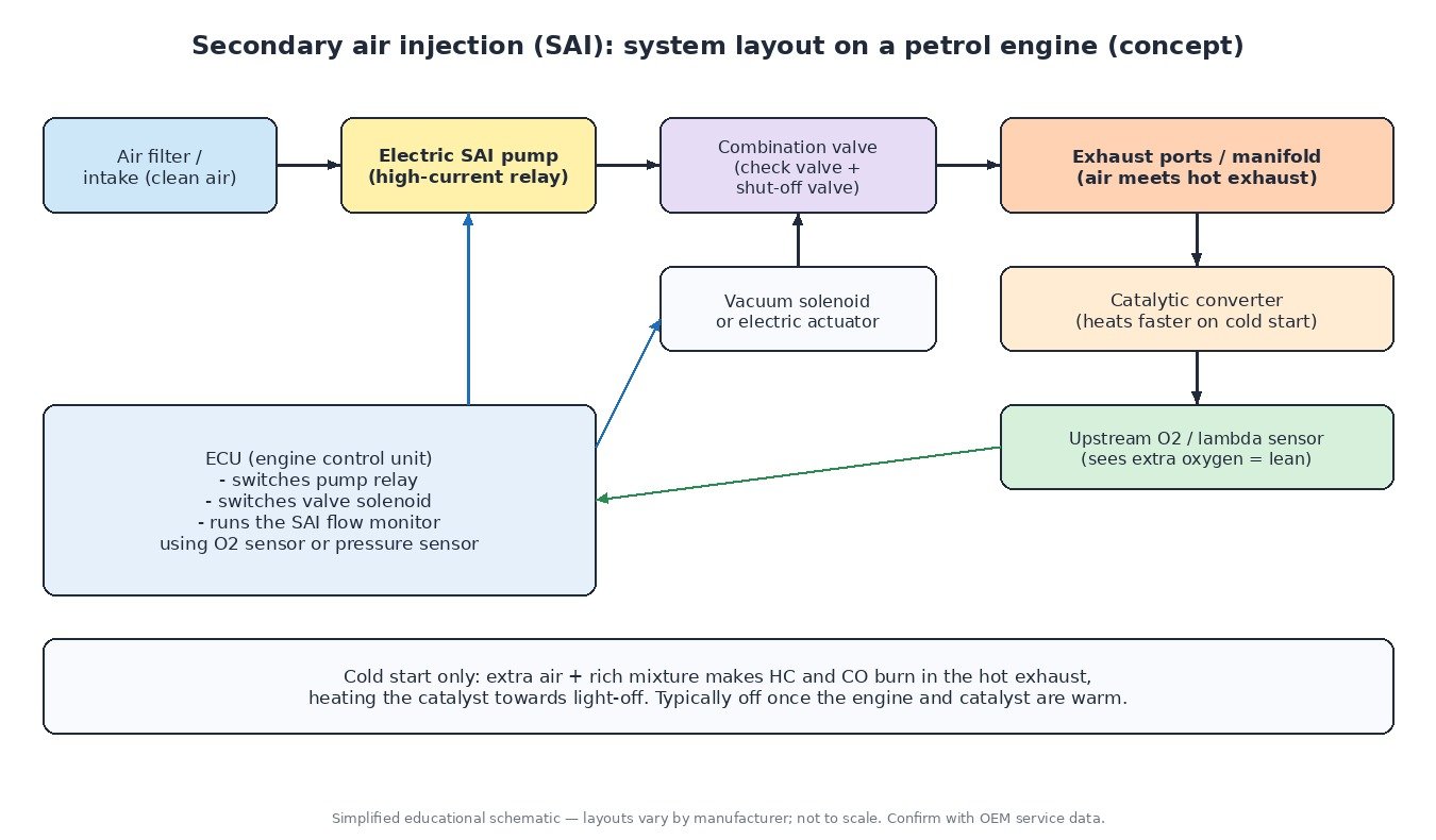
Secondary air injection pumps fresh air into the exhaust ports or manifold, close to the exhaust valves. The extra oxygen lets the unburned HC and CO keep oxidising in the hot exhaust. That reaction cleans up some of the emissions directly, and the heat it releases warms the catalyst faster. We covered catalyst light-off and efficiency monitoring in our catalytic converter guide.
Main components
- SAI pump – usually an electric blower drawing filtered air. It needs high current, so the ECU switches it through a relay and fuse. Older vehicles, mainly in North America, used belt-driven air pumps instead.
- Combination valve – a shut-off valve plus a one-way check valve. It opens only when the system is active and stops hot exhaust gas and condensation flowing back to the pump.
- Valve control – a vacuum solenoid that applies manifold vacuum to the valve diaphragm, or on some designs an electrically operated valve or one opened by pump pressure.
- Air passages – hoses and pipes, and on many engines drilled channels in the cylinder head leading to each exhaust port.
- Feedback – the upstream oxygen (lambda) sensor, and on some newer systems a dedicated SAI pressure sensor between the pump and valve.
How the ECU controls it
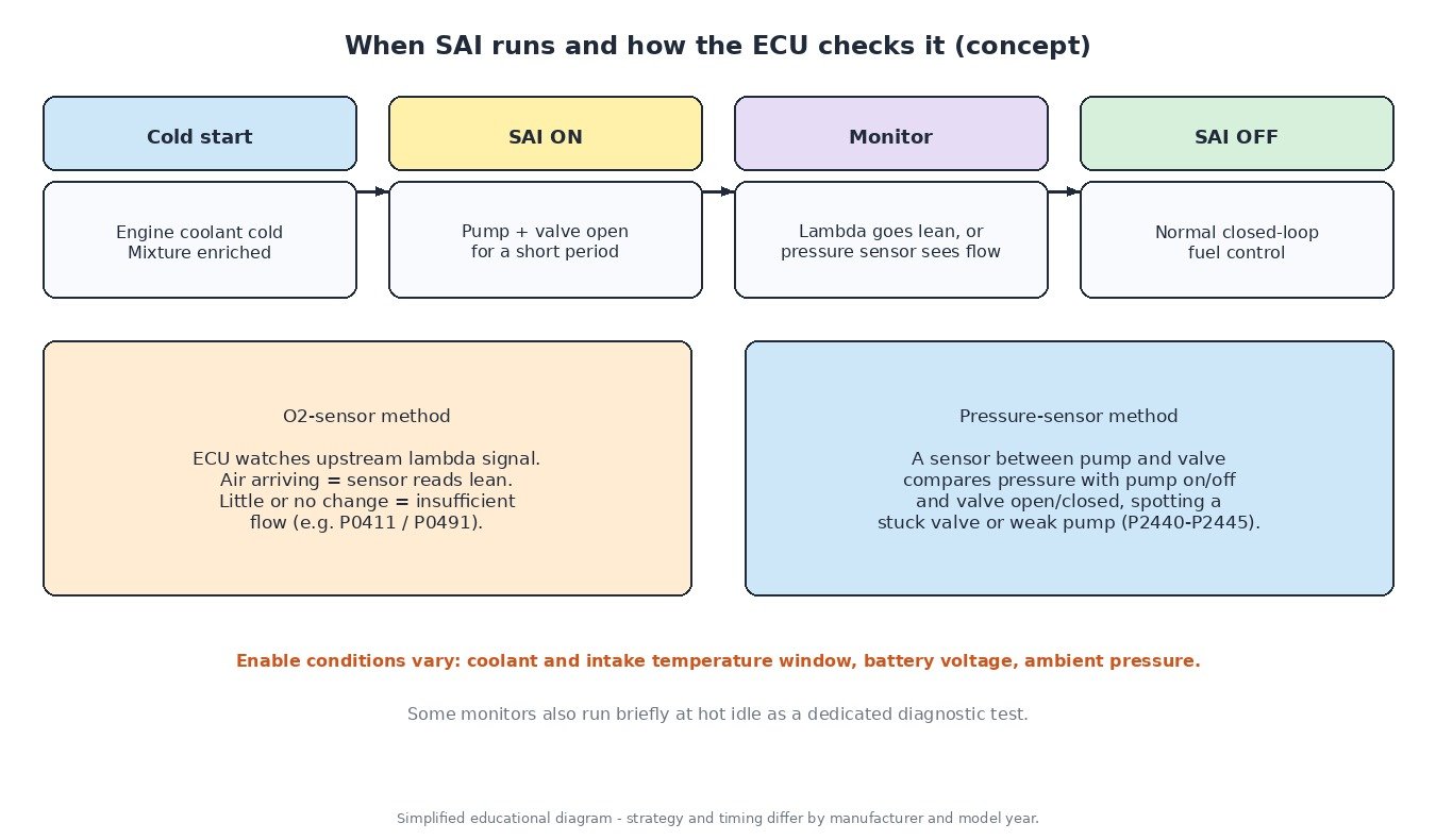
Secondary air is a cold-start strategy. When coolant and intake air temperatures are within a calibrated window, the ECU turns on the pump relay and opens the valve for a limited time after start-up, often well under two minutes. Exact enable conditions, run time and the fuelling used alongside it are calibrated by the manufacturer and differ between engines.
While SAI is active the upstream oxygen sensor reads lean, because it sees the extra air. The ECU knows this is expected, so it does not use that reading for normal closed-loop fuel trims at the same time. Once the system shuts off, normal lambda control resumes.
How the system is monitored
Because secondary air affects emissions, OBD regulations require it to be monitored. Two main methods are used:
- Oxygen sensor method: with the pump running, the ECU expects the upstream sensor to show a lean shift. If it barely changes, the ECU concludes that too little air is getting through and stores a flow code such as P0411 or the bank-specific P0491/P0492.
- Pressure sensor method: a sensor in the air path compares pressure with the pump on and off and the valve open and closed. This can tell a weak pump from a valve that is stuck open or stuck closed (the P2440–P2445 family).
Some ECUs run part of the test during the cold-start phase, others add a short dedicated test at hot idle. The result is shown in the “secondary air” readiness monitor, which your scan tool reports alongside catalyst, EVAP and oxygen sensor monitors.
Common failures
- Water in the pump: a leaking check valve lets exhaust condensation reach the pump, which then corrodes and seizes.
- Stuck valves: carbon and corrosion stop the combination valve opening or closing. A valve stuck open can also cause lean codes at warm idle.
- Blocked passages: on some engines the head channels to the exhaust ports clog with carbon, giving insufficient-flow codes even with a healthy pump.
- Electrical: blown fuse, failed relay, corroded pump connector or a chafed harness.
- Vacuum leaks: a split hose to the valve diaphragm means the valve never opens.
Diagnostic routine
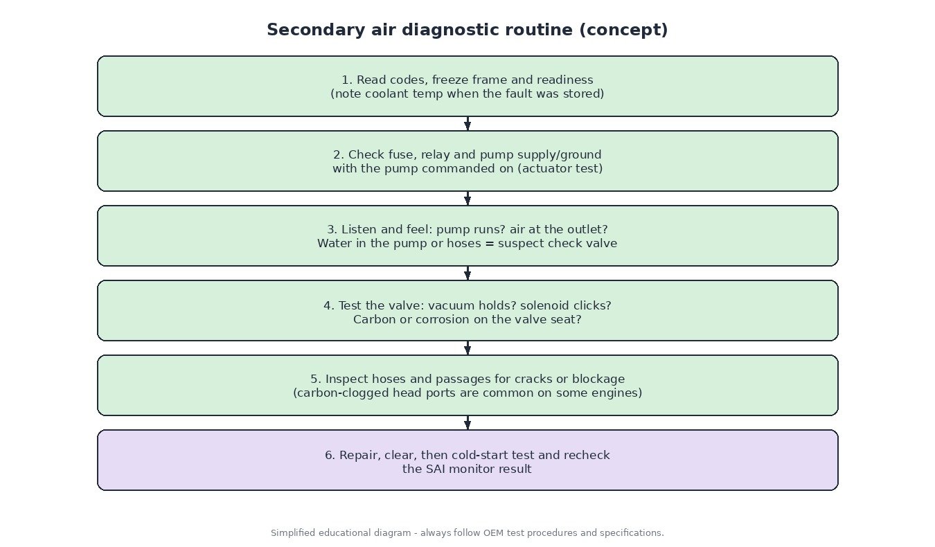
- Read all codes and the freeze frame. Note the coolant temperature when the fault was stored; most SAI faults are set at cold start.
- Use the scan tool’s actuator test to command the pump. Check the fuse, relay and voltage at the pump under load, not just with the circuit open.
- Listen for the pump and check for airflow at its outlet. Water or rust inside the pump hose points to a leaking check valve.
- Test the valve: apply vacuum and check it holds and opens, or check the solenoid clicks and passes vacuum when commanded.
- Inspect hoses and passages. If the pump and valve are good but flow is low, suspect carbon-blocked ports.
- After the repair, clear codes and do a genuine cold start (often an overnight soak) so the monitor can run, then recheck readiness.
Cars, trucks, machines and bikes
Cars and vans: common on many petrol engines from the late 1990s and 2000s, especially V6 and V8 units, and less common on newer direct-injection engines that use other catalyst-heating strategies such as retarded ignition and split injection.
Trucks: found on petrol pickups and light trucks. Heavy-duty diesels do not use secondary air; their aftertreatment relies on oxidation catalysts, DPF and SCR.
Agricultural and utility machines: most are diesel, so SAI is rare; small petrol engines generally do not use it.
Motorcycles: many bikes use a pulse secondary air system, where exhaust pressure pulses draw air through reed valves without a pump. On many fuel-injected bikes the ECU switches a solenoid valve to control it. A popping exhaust on deceleration or a leaking reed valve can point to this system.
Calibration notes
Secondary air is an emissions system and should stay fitted and working. When an ECU or TCU file is modified, the cold-start, SAI and catalyst-heating functions should be left as the manufacturer intended, and fuelling changes should be validated with a datalog of lambda after warm-up. If SAI codes appear after any ECU work, check the hardware first, then confirm the original software behaviour against the stock file.
Related fault codes (DTCs)
Generic OBD-II/EOBD codes (SAE J2012). Wording varies slightly between manufacturers, so always confirm with service information for the exact vehicle.
| Code | Meaning | Typical causes |
|---|---|---|
| P0410 | Secondary Air Injection System (malfunction) | General SAI fault: pump, valve, hoses, relay or wiring; read other stored SAI codes and freeze frame |
| P0411 | Secondary Air Injection System Incorrect Flow Detected | Weak or seized pump, stuck check/combination valve, cracked or disconnected hoses, carbon-blocked air passages |
| P0412 | Secondary Air Injection System Switching Valve A Circuit | Faulty vacuum/shut-off solenoid, damaged connector, open or shorted wiring, ECU driver fault |
| P0413 / P0414 | Secondary Air Injection System Switching Valve A Circuit Open / Shorted | Broken wire or connector, solenoid coil open or shorted, chafed harness |
| P0415 / P0416 / P0417 | Secondary Air Injection System Switching Valve B Circuit / Open / Shorted | Same as valve A, on systems with a second valve (for example, one per bank) |
| P0418 | Secondary Air Injection System Control “A” Circuit (pump relay A) | Failed pump relay, blown fuse, relay coil wiring fault, pump drawing excessive current |
| P0419 | Secondary Air Injection System Control “B” Circuit (pump relay B) | As P0418, on systems with a second pump or relay circuit |
| P0491 / P0492 | Secondary Air Injection System Insufficient Flow, Bank 1 / Bank 2 | Restricted hose or head passage on that bank, stuck valve, weak pump, exhaust leak, slow upstream O2 sensor |
| P2430 – P2433 | Secondary Air Injection System Air Flow/Pressure Sensor Circuit, Range/Performance, Low, High (Bank 1) | Faulty SAI pressure sensor, reference/ground wiring, blocked sensor port, or real flow problem seen as implausible pressure |
| P2440 / P2441 | Secondary Air Injection System Switching Valve Stuck Open / Stuck Closed, Bank 1 | Carbon, corrosion or moisture in the valve, failed diaphragm, vacuum supply leak; stuck open can let exhaust and water reach the pump |
| P2442 / P2443 | Secondary Air Injection System Switching Valve Stuck Open / Stuck Closed, Bank 2 | As P2440/P2441, on bank 2 |
| P2444 / P2445 | Secondary Air Injection System Pump Stuck On / Stuck Off, Bank 1 | Relay contacts welded or relay stuck (stuck on); seized pump, no power or ground, failed relay (stuck off) |
| P0171 / P0174 | System Too Lean, Bank 1 / Bank 2 | Not an SAI code itself, but a combination valve leaking air when it should be closed can add unmetered oxygen upstream of the O2 sensor |
Closing
Secondary air runs for only a minute or two, but a failed pump, valve or blocked port will keep the MIL on and the readiness monitor incomplete. Test the pump, valve and passages in order, then prove the repair with a real cold start.
Need a custom engineered ECU or TCU file built from your original read? Upload your file at ECUFileMarket.