
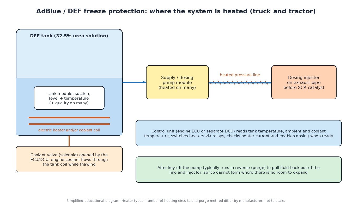
Selective catalytic reduction (SCR) cuts NOx emissions by spraying AdBlue, also sold as DEF (diesel exhaust fluid), into the exhaust ahead of a catalyst. The fluid is mostly water, so it freezes in a normal European winter. Every SCR-equipped truck, bus and modern tractor therefore carries a freeze protection system made of heaters, temperature sensors, a coolant valve and a purge routine, all managed by the engine ECU or a separate dosing control unit. Here is how it works at a cold start and at shutdown, and why heater faults are such a common winter complaint.
Why AdBlue needs heating at all
AdBlue is a solution of about 32.5% high-purity urea in demineralised water, specified in ISO 22241. That concentration is chosen because it has the lowest freezing point of any urea and water mixture, at about −11 °C. At this point urea and water freeze together, so after thawing the fluid has the same concentration as before and can be used normally.
The problems are mechanical and functional. Ice cannot be pumped, so a frozen system cannot dose, and the engine runs without NOx reduction until the fluid is liquid again. Water also expands as it freezes. A tank can be designed to tolerate this, but a full pressure line, pump chamber or dosing injector has no room to expand and can crack. Freeze protection therefore has two jobs: thaw the fluid quickly after a cold start, and empty the parts that cannot survive freezing when the engine is switched off.
The heated components
Layouts differ between manufacturers, but most heavy-duty systems combine:
- Tank module. A unit inside the tank that combines the suction point, level sensor and temperature sensor, and on many systems a quality (concentration) sensor. It usually carries an electric heater and, on trucks and tractors, often a coolant coil as well.
- Coolant valve. A solenoid valve that lets warm engine coolant flow through the coil in the tank. The control unit opens it while the fluid needs heating and closes it again, because AdBlue kept too hot for long periods starts to break down.
- Pump or supply module. Builds and controls dosing pressure. Many pump modules have their own heater because they sit outside the tank.
- Heated lines. The suction, return and pressure lines often have a resistance wire wound along their length, powered through a relay.
- Dosing injector. Mounted on the exhaust before the SCR catalyst. Usually not heated electrically; the purge keeps it empty while parked.
What the control unit does at a cold start
When the ignition is switched on, the ECU or DCU reads the tank temperature and usually ambient and coolant temperature. If the fluid could be frozen, it switches on the heating circuits and holds dosing off. It monitors heater current to confirm each circuit works, which is how open-circuit heater codes are set.
Thawing starts at the suction point, because the pump only needs liquid around its intake. Once the temperature model says enough fluid is available, the pump primes the line and the system checks that it can reach the expected pressure. Pressure that does not build up usually means ice in the line or a blocked filter. Dosing itself only begins when the catalyst is warm enough for the urea to decompose properly, so even a fully thawed system waits for exhaust temperature. The cold start and warm-up strategies the ECU applies elsewhere help here by bringing the exhaust up to temperature sooner.

Purge after shutdown
When the engine is switched off, the system does not simply stop. On most designs the pump runs in reverse, or a reversing valve changes the flow direction, and fluid is drawn back from the injector and pressure line into the tank. Air replaces the fluid, so there is nothing left to freeze in the narrow parts. This takes some time after key-off, which is why the control unit needs to stay powered through the main relay during the after-run. (see ECU power supply and the main relay).
Switching off the battery isolator immediately after stopping can interrupt the purge and leave fluid in the line. Many truck and machine operator manuals tell drivers to wait before turning the main switch off. Crystallised injectors and cracked lines after a frost often trace back to unfinished purges.
Tractors and off-road machines
Tractors and other Stage IV and Stage V machines use the same principles, but their duty cycle is harder on the system. Long periods at idle or light load in cold weather keep exhaust and coolant temperatures low, so thawing and dosing take longer. Correct purging, clean connectors and a working coolant valve matter even more than on a road truck.
Inducement and why heater faults escalate
Emission regulations require SCR vehicles and machines to warn the operator and then restrict performance if the system cannot reduce NOx as intended. Low fluid level, poor fluid quality and faults that prevent dosing all count. A heater fault that stops dosing for long enough can lead to a torque reduction or speed limit on a truck, or reduced power on a tractor. Heavy-duty engines usually report these faults as J1939 SPN and FMI codes. Examples include SPN 1761 for DEF tank level and SPN 3031 for DEF tank temperature; our guide to J1939 fault codes explains how to read them.
Diagnosis in practice
Start by reading every module, because many trucks have a separate dosing control unit, and note the tank temperature in the freeze frame. Check level and concentration with a refractometer: fluid topped up with water freezes at a higher temperature and fails the quality check. Then work through the heating circuits one at a time: fuses, relays, grounds and the line connectors near the chassis rail, which corrode easily, followed by heater resistance or current against the specification. Test the coolant valve with a diagnostic tool, since a valve stuck closed slows thawing and one stuck open overheats the fluid in summer. Finally, compare tank temperature with ambient after a cold soak, run the dosing system test and listen for the purge after key-off.
Never add antifreeze, diesel or additives to AdBlue; they can damage the pump, injector and catalyst.

What this means for ECU calibration work
Heater control, purge timing, dosing enable conditions and inducement logic are all part of the engine or dosing control unit software. When a file is modified for more power or better driveability, these functions should stay intact so the SCR system keeps working through the winter. Fix stored heater or quality faults before any tuning work.
Related fault codes (DTCs)
Light and medium-duty diesels report generic OBD codes like these; heavy trucks and many tractors use J1939 SPN/FMI codes. The heater letters “A” and “B” are assigned by the manufacturer, so check which physical heater each one refers to.
| Code | Meaning | Typical causes |
|---|---|---|
| P20B9 | Reductant heater “A” control circuit/open | Open heater element, blown fuse or failed relay, corroded or water-filled connector, damaged harness near the tank or line |
| P20BD | Reductant heater “B” control circuit/open | Same circuit faults on the second heating circuit (often a heated line or pump heater, depending on the manufacturer) |
| P205B | Reductant tank temperature sensor circuit range/performance | Sensor reading implausible against ambient or coolant temperature after a cold soak, failing tank module, wiring resistance |
| P205C | Reductant tank temperature sensor circuit low | Signal shorted to ground, damaged harness, faulty sensor in the tank module |
| P205D | Reductant tank temperature sensor circuit high | Open circuit, unplugged or corroded connector, faulty sensor |
| P20E8 | Reductant pressure too low | Fluid still frozen or partially thawed, blocked suction filter, crystals in line, air leak at line connectors, weak pump |
| P204F | Reductant system performance bank 1 | Dosing not achievable as commanded: frozen or blocked line, crystallised injector, pump or pressure sensor faults |
| P203F | Reductant level too low | Low tank level, frozen fluid around the level sensor giving a false reading, faulty level sensor |
| P207F | Reductant quality performance | Fluid diluted with water or contaminated, degraded fluid after hot storage, quality sensor fault |
| P20EE | SCR NOx catalyst efficiency below threshold bank 1 | Too little or no dosing for a long period (heating or purge faults), poor fluid quality, NOx sensor faults, catalyst damage |
Generic SAE J2012 / ISO 15031-6 code meanings shown. Code support and descriptions vary by manufacturer; always confirm with service data for your vehicle or machine.
Planning a tune for your truck, tractor or car? Upload your original ECU read to ECUFileMarket and get a file prepared for your exact hardware and software version.