
Anyone who has spent a day with a front loader knows how many times a tractor changes direction: forward into the heap, back out, forward to the trailer, back again. On older tractors every change meant pressing the clutch, moving a lever and releasing the clutch again. A power shuttle does the same job at the flick of a lever on the steering column. This article explains how an electro-hydraulic power shuttle works, which sensors and valves the transmission controller uses, why calibration matters and how to approach faults on the workshop floor.
Mechanical shuttle vs power shuttle
A synchro shuttle uses a synchroniser to select forward or reverse. The operator still needs the clutch pedal, and the synchro has to match speeds, so frequent direction changes wear both the clutch and the operator.
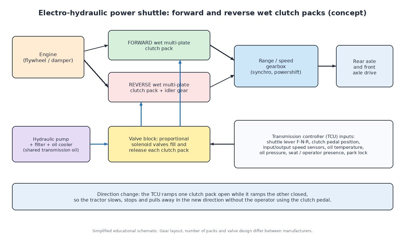
A power shuttle replaces the synchro with two wet multi-plate clutch packs: one for forward and one for reverse, where the reverse path runs through an extra idler gear. Both packs sit in transmission oil, which cools the plates and lets them slip in a controlled way. The direction is changed by releasing one pack and engaging the other with hydraulic pressure, so there is no need to touch the clutch pedal. Many tractors also use the same packs as the main clutch, which is why the pedal on these machines is often only an electrical input to the controller, not a mechanical link.
The hardware
- Clutch packs: alternating friction and steel plates pressed together by a hydraulic piston, with springs pushing the piston back when pressure is released.
- Hydraulic supply: a pump, filter and oil cooler, usually sharing the transmission oil with other functions such as lubrication, PTO and sometimes the rear hydraulics.
- Valve block: proportional solenoid valves that control the pressure in each pack. These work like the variable force solenoids described in our guide to transmission shift solenoids and pressure control.
- Controller: a transmission control unit (TCU), sometimes combined with other tractor functions, which decides when and how fast each pack fills.
Inputs the controller watches
The controller needs a clear picture of what the operator wants and what the driveline is doing:
- Shuttle lever: forward, neutral and reverse positions, often with redundant switches so that a single broken contact does not select the wrong direction.
- Clutch pedal position: a sensor (often with two signals for plausibility) that lets the operator inch the tractor by modulating pack pressure.
- Speed sensors: input and output shaft speed, used to judge slip, ground speed and when a pack is fully locked.
- Oil temperature and pressure: cold oil flows slowly and changes fill times, while hot oil warns of excessive slip. Our transmission fluid temperature sensor guide covers the thermal strategies.
- Safety inputs: seat or operator-presence switch, park lock and sometimes brake pedal switches. Many tractors drop to neutral if the operator leaves the seat while a direction is engaged.
- Engine data over CAN: engine speed and torque information, shared on the tractor network much like the data used by ISOBUS implements.
What happens during a direction change
When the operator pulls the lever from forward to reverse while moving, the controller releases pressure on the forward pack. It then fast-fills the reverse pack to take up the piston clearance, drops to a lower controlled pressure so the pack slips, and ramps pressure up as the tractor slows, stops and starts moving backwards. Once the speed sensors show that slip has ended, the pack is held at full pressure.
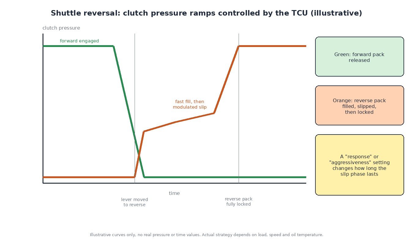
The slip phase is where the energy goes. A heavy tractor with a full loader bucket, changing direction at speed, turns a lot of kinetic energy into heat in the clutch plates and oil. That is why many controllers limit the shuttle at higher speeds, adapt the ramps to oil temperature and load, and protect the packs if temperature rises.
Shuttle response settings
Many tractors let the operator choose how aggressive the shuttle feels, from soft for transport and trailer work to quick for loader work. In practice this setting changes the length and shape of the slip phase, not the clutch hardware.
Calibration: why it matters
The fill time and the pressure at which a pack starts to transmit torque vary with plate wear, piston seals, spring condition and valve tolerances. Controllers therefore store learned values, much like other ECU adaptation values. After replacing plates, a valve block, a solenoid or the controller itself, the manufacturer’s clutch calibration routine normally has to be run with the oil at the specified temperature. Skipping it is a common reason for harsh or delayed engagement after a repair.
Diagnosis tips
- Start with the basics: oil level, correct oil specification, filter condition and oil temperature. Many shuttle complaints are hydraulic, not electronic.
- Read stored codes from the transmission controller and note whether they are active or historic.
- Check the inputs live: lever positions, pedal sensor signals, seat switch and speed sensors in the diagnostic software. A flickering lever signal can mimic a clutch fault.
- Measure pressures at the test ports if the maker provides them and compare with service data.
- Check supply voltage and grounds: low voltage affects solenoid current and controller behaviour.
- Run the calibration once the cause is fixed, then road test with warm oil.

Tuning note
An engine remap changes the torque the shuttle packs must hold and the heat they absorb during reversals. Keep torque increases within what the driveline is built for, and remember that the transmission controller may use engine torque messages to set clutch pressures. For more on how gearbox controllers work in general, see how a TCU controls an automatic transmission.
Related fault codes (DTCs)
Tractor transmissions usually report faults as SAE J1939 suspect parameter numbers (SPN) with a failure mode identifier (FMI), alongside manufacturer-specific codes. Machines that use OBD-style P-codes may show the generic codes below.
| Code | Meaning | Typical causes |
|---|---|---|
| J1939 SPN 161 (+ FMI) | Transmission input shaft speed | Input speed sensor faulty, wrong air gap or debris on the tip, damaged wiring or connector, signal implausible against engine speed |
| J1939 SPN 191 (+ FMI) | Transmission output shaft speed | Output speed sensor or tone wheel damage, open or shorted wiring, sensor loose after gearbox work |
| J1939 SPN 177 (+ FMI) | Transmission oil temperature | Temperature sensor or circuit fault, real overheating from slipping clutches, blocked oil cooler, low oil level |
| J1939 SPN 127 (+ FMI) | Transmission oil pressure | Low oil level, blocked filter, worn pump, internal leakage at seals, pressure sensor or wiring fault |
| J1939 SPN 523 (+ FMI) | Transmission current gear | Gear or direction actually engaged does not match the expected value: slipping pack, valve fault, speed sensor error |
| J1939 SPN 524 (+ FMI) | Transmission selected gear | Shuttle lever or selector signal implausible, lever switch or wiring fault, CAN message missing |
| J1939 SPN 168 (+ FMI) | Battery potential / power input 1 | Low or unstable supply voltage, poor grounds, weak batteries or alternator, causing solenoids and controller to misbehave |
| P0700 | Transmission control system (MIL request) | The transmission controller has stored its own fault; read it for the detailed code |
| P0715 | Input/turbine speed sensor “A” circuit | Input speed sensor, its wiring or connector, excessive gap, metal debris on the sensor |
| P0720 | Output speed sensor circuit | Output speed sensor, wiring or connector fault, damaged reluctor |
| P0868 | Transmission fluid pressure low | Low oil level, clogged filter, worn pump, internal leaks, faulty pressure sensor |
| P0562 | System voltage low | Weak battery, charging system fault, high resistance in supply or ground circuits |
Standard SAE J1939 SPN names and generic SAE P-code meanings shown. The FMI tells you the type of failure (for example voltage high or low, data erratic). Always check manufacturer data for exact definitions.
Working on a tractor engine file? Upload your original ECU read to ECUFileMarket and get a calibration prepared for your exact software version.