
When an ECU cannot be read through the OBD socket, or when a workshop wants the most complete backup possible, it is time for a direct-connection tool. Alientech’s K-TAG is one of the best-known tools in this group. It connects to the ECU itself, on the bench, rather than to the vehicle’s diagnostic port. This article explains what a K-TAG-type tool does, the connection methods it uses, how a safe read/write session works and which mistakes cause most of the trouble. The principles apply equally to cars, vans, trucks, tractors and motorcycles.

What a direct-connection tool is
An OBD tool talks to the ECU through the same diagnostic protocol a scan tool uses, and it depends on the ECU’s own software allowing a read or write. A direct-connection tool such as K-TAG works at a lower level. The ECU is removed from the vehicle and powered from a bench supply, and the tool connects either to the ECU connector or straight to the circuit board. Because it talks to the microcontroller rather than to the running application, it can often read ECUs that are locked over OBD and make a fuller backup: program flash, calibration data, EEPROM and, depending on the ECU and licence, processor or ID data.
The tool is driven by a PC program. Alientech’s tools use the K-Suite software. For each supported ECU the software shows which method applies and gives a connection diagram showing where each wire or probe goes. Supported ECU families and protocols depend on the tool’s licence and activated protocols, so always check the software’s ECU list before taking a job.
The connection methods
Bench mode
Many recent ECUs can be read and written on the bench through their own connector, with no need to open the case. The tool supplies power, ignition and the communication lines through a cable harness wired as shown in the software. This is the least invasive direct method.
Boot mode
In boot mode the microcontroller is forced to start in its internal boot loader instead of the normal application. This usually means opening the case and connecting a wire, sometimes through a resistor, to a specific boot pin or test point on the board. Boot access gets around many software protections, but it needs care: a wrong point or a slipped probe can damage the board.
BDM and JTAG
Older and some current microcontrollers have debug ports, such as BDM on certain Motorola/Freescale families, and JTAG or similar ports on others. The tool connects to these pads using a frame and probes or soldered wires. These methods read the memory directly and are common on older diesel and petrol ECUs, on many motorcycle units and on some truck and agricultural controllers.
A safe read/write workflow

- Identify the ECU. Record the label, hardware and software numbers and, if the case is opened, the microcontroller. The same housing can contain different hardware.
- Use the matching connection diagram. Pick the exact entry in the software and follow its pinout. Guessing pins is the quickest way to kill an ECU.
- Get the power right. Use a stable bench power supply with the voltage the software asks for, solid ground connections and short, secure leads. Many failed sessions are really power problems.
- Back up everything first. Save every area the tool can read. Ideally, read twice and compare the two files. If they differ, find out why before going on.
- Modify and correct checksums. A modified calibration must have valid checksums before it is written. Otherwise the ECU may not start or may log a memory fault.
- Write, verify and test. Write the file, let the tool finish completely, refit the ECU, clear the fault memory, check live data and test drive.
What is actually in the backup
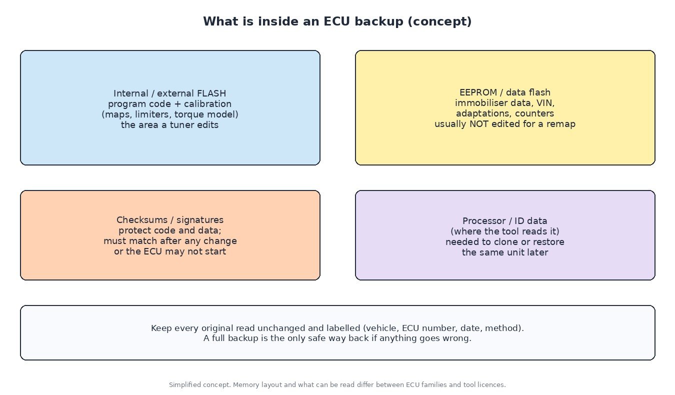
The program flash holds the software and the calibration: the maps, limiters and torque model a tuner works on. The EEPROM or data flash holds vehicle-specific data such as immobiliser information, VIN, adaptation values and counters. For a normal remap that area is not edited, but it is essential if the ECU ever has to be restored or replaced. Keep every original read unchanged, labelled with the vehicle, ECU number, date and read method, and store it somewhere other than the workshop laptop.
Common mistakes and how to avoid them
- Unstable power: a weak or noisy supply can make a read fail or produce a corrupt file.
- Laptop interruptions: sleep mode, USB power saving, a cheap hub or a dying battery can break a write halfway. Disable power saving and connect directly.
- Static and mechanical damage: use ESD protection, open housings carefully and never lever against components. Some cases are glued and need patience.
- Writing a file for different software: a calibration only belongs on the exact software version it was made for.
- Panic after a failed write: do not keep power-cycling. Keep the backup safe and follow the tool’s recovery procedure. See our guide on failed ECU write recovery.
Trucks, tractors and motorcycles
Heavy-duty and agricultural ECUs are often sealed against water and vibration, so opening them takes extra care and the housing must be resealed properly afterwards. Some run from 24 V systems on the vehicle, but on the bench always use the supply voltage the tool software specifies. Motorcycle ECUs are small and tightly packed, and the boot or BDM points can be tiny, so a good frame, magnification and steady probes make all the difference. For an overview of the different read paths, see ECU reading methods: OBD, bench and boot.
When to choose direct connection over OBD
Use OBD when the ECU is fully supported there and a quick, non-invasive job is the goal. Choose bench or boot when OBD is locked or unsupported, when you need a complete backup including EEPROM, when you are preparing to clone or replace a unit, or when a previous OBD write failed. Many workshops do both: a quick OBD identification first, then a bench or boot read when the job calls for it.
Related fault codes (DTCs)
These generic codes often show up after ECU work goes wrong, or point to problems that must be fixed before any programming is attempted:
| Code | Meaning | Typical causes |
|---|---|---|
| P0601 | Internal Control Module Memory Check Sum Error | Modified file written without correct checksums, incomplete or corrupted write, internal memory fault |
| P0602 | Control Module Programming Error | ECU not programmed or programming not completed, interrupted flash session, wrong software for the hardware |
| P0603 | Internal Control Module Keep Alive Memory (KAM) Error | Battery or permanent supply disconnected, poor ECU ground, internal memory fault |
| P0604 | Internal Control Module Random Access Memory (RAM) Error | Internal ECU fault, often after water ingress, overheating or a damaged board |
| P0605 | Internal Control Module Read Only Memory (ROM) Error | Corrupted flash content, failed or incomplete write, internal ECU fault |
| P0606 | Control Module Processor | Internal processor or monitoring fault, supply/ground problems, corrupted software |
| P0607 | Control Module Performance | Internal ECU fault, supply voltage problems, software inconsistency after a write |
| P0630 | VIN Not Programmed or Incompatible – ECM/PCM | Replacement or cloned ECU without the vehicle’s VIN, EEPROM data from another vehicle, coding not completed |
| P0562 | System Voltage Low | Weak battery, poor charging, bad grounds, unstable power supply during bench or vehicle work |
| U0100 | Lost Communication With ECM/PCM “A” | ECU not powered or not booting after a failed write, CAN wiring or connector fault, ECU left disconnected |
Note: generic SAE descriptions are shown. Manufacturers may add their own codes for programming and memory faults; always check the vehicle’s service data.
Have a backup read and need a tuned file matched to your exact ECU hardware and software? Upload it to the file service at ECUFileMarket.