
A continuously variable transmission (CVT) has no fixed gears. Instead of switching between ratios like a conventional automatic, it changes the ratio smoothly between a lowest and a highest value, so the engine can stay at the speed that suits the driver’s request. Many small and mid-size cars, several hybrids and almost every automatic scooter use some form of CVT. For anyone who works with transmission control units (TCUs), diagnostics or engine calibration, it helps to understand how the variator works and how closely the TCU depends on information from the engine ECU.

The variator: two pulleys and a belt or chain
The heart of a car CVT is the variator. It has two pulleys: a primary (drive) pulley connected to the engine side and a secondary (driven) pulley connected to the wheels. Each pulley is made of two conical halves called sheaves. One sheave is fixed to the shaft and the other can slide along it, pushed by hydraulic pressure.
When the movable sheave moves towards the fixed one, the V-shaped groove narrows and the belt is forced to run on a larger radius. When the sheaves move apart, the belt drops to a smaller radius. Because the belt length is fixed, the two pulleys always work in opposite directions:
- Low ratio (pulling away): small radius on the primary pulley, large radius on the secondary. The engine turns many times for each turn of the output shaft.
- Overdrive (cruising): large radius on the primary pulley, small radius on the secondary. Engine speed drops at a given road speed.
Two main types of belt are used. The steel push belt is built from hundreds of thin steel elements held together by packs of thin steel bands; it transmits torque by the elements pushing against each other. The chain type uses plate links joined by pins whose ends contact the sheaves; it transmits torque by pulling. Both rely on friction between steel surfaces lubricated by a special fluid, which is why fluid type and condition matter so much.
Around the variator: launch device and direction
A variator cannot start the car from standstill on its own, and it cannot reverse. Most car CVTs therefore add:
- A launch device, usually a torque converter with a lockup clutch, or on some designs a wet multi-plate clutch. Our article on torque converters and lockup control explains this part in detail.
- A planetary gear set with a forward clutch and a reverse brake to select drive or reverse.
- A final drive and differential. Some designs also add a small two-speed auxiliary gear set behind the variator to widen the overall ratio spread.
An oil pump driven by the engine supplies the pressure for all of this, regulated by solenoids in the valve body.
How the TCU controls a CVT

The TCU does two jobs at the same time: it sets the ratio and it makes sure the belt does not slip.
Ratio control
Instead of a shift map with gear changes, a CVT calibration usually works with a target primary pulley speed, which is effectively a target engine speed. It is looked up from pedal position or torque request and vehicle speed, then adjusted for drive mode, fluid temperature, gradient and other conditions. The TCU calculates the actual ratio from the primary and secondary pulley speed sensors and moves the ratio-setting pulley until actual matches target. Many modern calibrations also simulate stepped “gears” during hard acceleration or in manual mode, because drivers dislike the constant-rpm feel.
Clamping force
The other pulley’s pressure sets how hard the sheaves squeeze the belt. Too little clamping and the belt slips, which quickly damages the belt and the sheave surfaces. Too much clamping wastes energy in the oil pump and adds wear. The TCU therefore calculates the required clamping force from the torque that reaches the variator, plus a safety margin. That torque value normally comes from the engine ECU over CAN, which links CVT control directly to the engine torque model. Which pulley handles ratio and which handles clamping depends on the design.
Protection and fail-safe
If the TCU detects slip, a ratio it cannot reach, high fluid temperature or a sensor fault, it can request an engine torque reduction, store a code and switch to a fail-safe strategy with a limited ratio range. The fluid temperature sensor and the pressure control solenoids play a central role here.
Scooters, ATVs and tractors
Automatic scooters, many ATVs/UTVs and snowmobiles use a rubber V-belt CVT that is purely mechanical. Centrifugal rollers or weights in the drive pulley push the sheaves together as engine speed rises, while a spring-loaded, torque-sensing driven pulley resists. There is no TCU; the behaviour is tuned with roller weights, springs and clutch settings. Tractors use a completely different concept, the hydro-mechanical power-split CVT, covered in our guide to how a tractor CVT works.
Diagnosing common CVT complaints
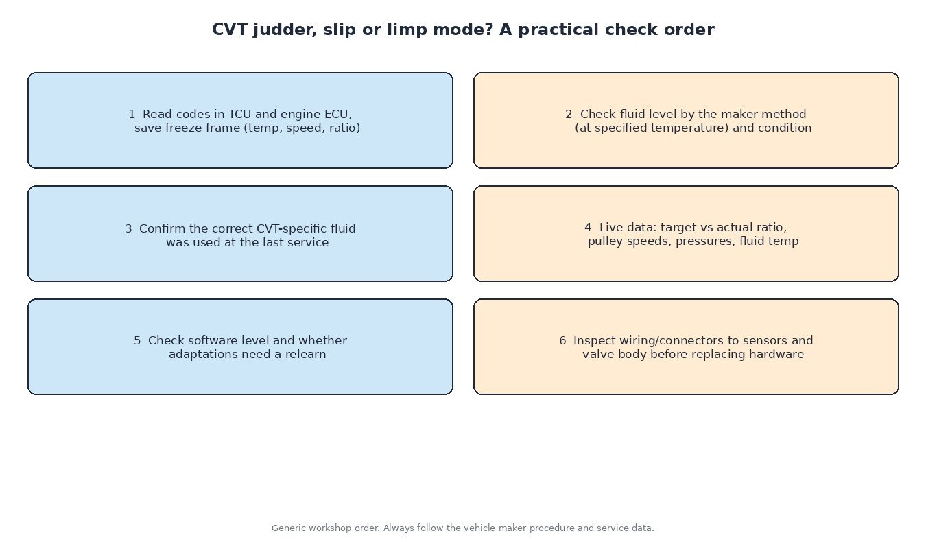
Typical complaints are judder when pulling away, a whine or drone that changes with ratio, engine speed flaring without matching acceleration, and a fail-safe mode with weak acceleration or limited top speed. A sensible order of work:
- Read codes in both the TCU and the engine ECU and save the freeze frame data. Engine faults that affect the torque signal can upset CVT control.
- Check fluid level using the maker’s method, which often requires a specific fluid temperature, and inspect the fluid condition.
- Confirm that the correct CVT-specific fluid was used. Conventional automatic transmission fluid does not have the right friction properties for a steel belt or chain.
- In live data, compare target and actual ratio, both pulley speeds, line or pulley pressures and fluid temperature during a road test.
- Check the software level and whether adaptations need to be reset or relearned after a fluid change, valve body replacement or repair, as required by the maker.
- Inspect wiring and connectors before condemning the transmission.
What this means for tuning
Because clamping force is calculated from the engine torque signal, an engine remap on a CVT car must respect the transmission’s torque limits. If the actual torque rises but the signal sent to the TCU no longer represents it accurately, clamping may be too low and the belt can slip. Many CVTs have conservative torque capacity, so a responsible calibration keeps transmission protection in place and is built on the original read of the exact engine ECU and TCU software. Always keep full original backups of both units.
Related fault codes (DTCs)
These generic codes are often seen with CVT faults. Many manufacturers also use their own codes for belt slip, ratio errors and pulley pressure, so always read the TCU directly.
| Code | Meaning | Typical causes |
|---|---|---|
| P0700 | Transmission control system (MIL request) | The TCU has stored its own fault and asked the engine ECU to light the MIL; read the TCU for the actual code |
| P0711 | Transmission fluid temperature sensor “A” circuit range/performance | Sensor drift, implausible reading versus running time, wiring or connector fault, sensor on internal harness |
| P0715 | Input/turbine speed sensor “A” circuit | Primary pulley or input speed sensor fault, wiring, connector, damaged sensor target |
| P0720 | Output speed sensor circuit | Secondary pulley or output speed sensor fault, wiring or connector problem, metal debris on the sensor |
| P0730 | Incorrect gear ratio | Actual ratio not matching the commanded ratio: belt or chain slip, low or degraded fluid, pressure control problem, speed sensor error |
| P0741 | Torque converter clutch circuit performance or stuck off | Lockup clutch wear or judder, TCC solenoid or valve fault, wrong or worn fluid |
| P0746 | Pressure control solenoid “A” performance/stuck off | Sticking solenoid or valve in the valve body, contaminated fluid, low line pressure |
| P0776 | Pressure control solenoid “B” performance/stuck off | Sticking solenoid or valve, debris in the fluid, internal leak |
| P0841 | Transmission fluid pressure sensor/switch “A” circuit range/performance | Pressure sensor fault, wiring, actual pressure out of range from a pump, valve or leak problem |
| P0868 | Transmission fluid pressure low | Low fluid level, worn oil pump, clogged strainer or filter, internal leakage, pressure regulator fault |
| P0218 | Transmission fluid over temperature condition | Towing or long climbs, blocked or bypassed cooler, low fluid, sustained slip, temperature sensor fault |
Generic SAE J2012 code meanings shown. Exact wording and enable conditions vary by manufacturer; always check service data.
Need a tuning file built on your original ECU read? Upload it to ECUFileMarket and get a file prepared for your exact hardware and software version.