
A modern tractor can creep at walking pace with a heavy implement, hold an exact PTO speed and cruise on the road at transport speed without a single gear lever. The component behind this is the hydro-mechanical continuously variable transmission (CVT). This guide explains how a power-split CVT works, what the transmission control unit (TCU) does, how it cooperates with the engine ECU, and what to check when a CVT tractor shows faults.
Why tractors use CVTs
Field work asks for very different speeds at the same time as very different loads. Ploughing needs high tractive force at low speed, spraying needs a constant ground speed, a PTO-driven implement needs a constant engine speed, and road transport needs efficiency at high speed. A stepped powershift gearbox always compromises between two gears. A CVT removes the steps: the ratio can be any value inside its range, so the control system can choose ground speed and engine speed independently.
The hydrostatic part: pump and motor
A pure hydrostatic drive uses a variable-displacement axial piston pump driving a hydraulic motor. Tilting the pump’s swashplate changes how much oil it delivers per revolution, and therefore how fast the motor turns. Swing the swashplate through zero and the motor stops, then reverses. That makes hydrostatic drives smooth and easy to control and common on compact tractors, telehandlers and combines.
The downside is efficiency: power passing through a pump and motor loses energy as heat through leakage and friction. For a large tractor working at full power all day, that wastes fuel and overheats the oil.
Power split: mixing gears and hydraulics
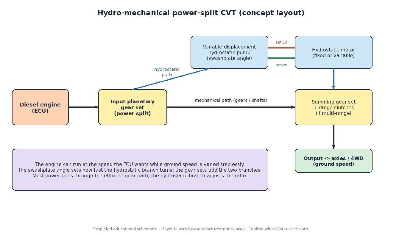
A hydro-mechanical CVT solves this with one or more planetary gear sets. Engine power enters the transmission and is split into two branches:
- Mechanical branch – gears and shafts, very efficient.
- Hydrostatic branch – the variable pump and the motor, used to change the ratio.
A planetary set (or a summing gear stage) adds the two speeds back together at the output. Because a planetary gear set relates three speeds (sun, carrier, ring), changing the speed of one member through the hydrostatic branch changes the output speed while the engine keeps turning at the speed the controller wants. In most of the operating range the larger part of the power flows mechanically, and the hydrostatic branch only carries the part needed to set the ratio.
Single-range and multi-range designs
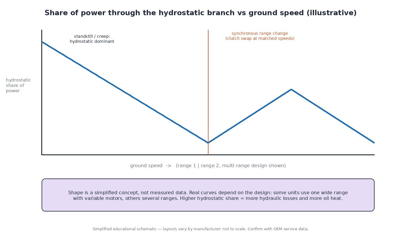
Designs differ between manufacturers. Some use one wide range with large variable-displacement hydraulic units. Others use two or more mechanical ranges selected by wet clutches. In multi-range designs the range change happens at a synchronous point where the clutch members already turn at the same speed, so the swap is seamless and the driver does not feel a shift. The share of power going through hydraulics rises and falls across each range, and the transmission is most efficient where that share is small.
Active standstill
Because the ratio can reach “infinite” (output speed zero with the engine running), many CVT tractors can hold the machine stationary on a slope with the drive engaged and no clutch pedal used. This is often called active standstill or powered zero. For longer stops the park lock or brakes must still be applied according to the operator’s manual.
What the TCU controls
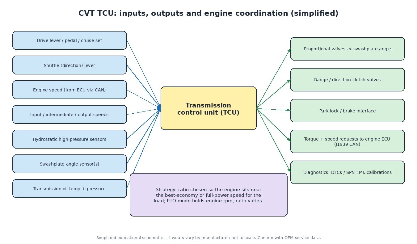
The TCU turns the driver’s request into a ratio. Typical inputs are the drive lever or pedal, the shuttle (direction) lever, cruise speed settings, engine speed received over CAN, several shaft speed sensors, hydrostatic high-pressure sensors, swashplate angle sensors, and transmission oil temperature and pressure. Its main outputs are proportional valves that set the swashplate angle, valves for the range and direction clutches, the park lock interface, and CAN messages to the engine ECU.
The control is closed loop. The TCU calculates the target ratio from the requested ground speed and the engine speed, measures the actual ratio from the speed sensors, and corrects the swashplate angle continuously.
Engine and transmission management
The biggest advantage of a CVT appears when the TCU and the engine ECU work together over the J1939 CAN bus. Common strategies include:
- Economy operation – at light load the system lowers engine speed and compensates with ratio, so the same ground speed is held with fewer revolutions.
- Load limit / droop setting – the driver sets how far engine speed may drop under load. When a heavy section of the field pulls the engine down to that limit, the TCU reduces ground speed instead of letting the engine stall or lug.
- PTO mode – engine speed is held constant for the PTO shaft (for example a 540 or 1000 rpm setting), and only the ratio varies to change ground speed.
- Torque and speed requests – the TCU can ask the engine ECU for a specific speed or torque, for example during range changes, direction reversal or when protecting the transmission.
Diagnostics tips for CVT tractors
- Read every module. A CVT complaint may come from the engine ECU, the TCU or a CAN problem. Read the fault memory of all control units, including J1939 active (DM1) and previously active (DM2) codes.
- Check the oil first. Correct level, the specified oil grade, clean filters and a working oil cooler matter a lot. Overheating and pressure codes often start with oil condition or a blocked cooler.
- Watch live data. Compare commanded and actual ratio, swashplate angle, hydrostatic pressures and shaft speeds. A ratio that drifts under load points towards internal leakage or a control problem.
- Supply voltage and grounds. Proportional valves and sensors are sensitive to low voltage. Check batteries, the charging system and module grounds before replacing parts.
- Run the calibrations. After replacing the TCU, a hydraulic unit, a sensor or clutches, the manufacturer’s calibration procedures (for example neutral/zero position and clutch calibration) are normally required. Skipping them can cause jerky starts or creeping in neutral.
What this means for engine calibration
When an engine in a CVT tractor is remapped, the transmission is part of the system. The TCU knows the engine’s torque through CAN messages, and the transmission has its own torque limits for clutches, gears and hydraulic units. A sensible calibration keeps torque changes within the drivetrain’s capability, keeps CAN torque reporting plausible, and leaves protection functions and the emissions system (DPF, EGR, SCR/AdBlue) fully working. Always start from an original read of the ECU and keep it as a backup.
Related fault codes (DTCs)
| Code | Meaning | Typical causes |
|---|---|---|
| P0700 | Transmission Control System Malfunction (MIL request) | The TCU has stored its own fault and asks the engine ECU to report it; read the TCU memory for the specific code |
| P0710–P0713 | Transmission Fluid Temperature Sensor A Circuit / Range/Performance / Low / High | Open or shorted sensor or wiring, corroded connector, implausible reading versus other temperatures |
| P0218 | Transmission Fluid Over Temperature Condition | Long periods at high hydrostatic share (heavy draft work at very low speed), blocked oil cooler, low oil level, wrong oil, clogged filter, internal leakage |
| P0715 | Input/Turbine Speed Sensor A Circuit | Faulty speed sensor, air gap or debris on the sensor tip, damaged wiring or connector |
| P0720 | Output Speed Sensor Circuit | Sensor or wiring fault, damaged target wheel, metallic debris on a magnetic sensor |
| P0730 | Incorrect Gear Ratio | Measured input/output speed ratio does not match the commanded ratio: hydrostatic unit leakage, slipping clutch, swashplate control fault, speed sensor error |
| P0840 / P0841 | Transmission Fluid Pressure Sensor/Switch A Circuit / Circuit Range/Performance | Sensor or wiring fault, low system pressure, worn charge pump, blocked filter |
| P0868 | Transmission Fluid Pressure Low | Low oil level, aerated oil, blocked suction filter, worn charge pump, internal leakage, stuck relief valve |
| U0100 / U0101 | Lost Communication With ECM/PCM “A” / Lost Communication With TCM | CAN wiring damage, termination problems, connector corrosion, module power or ground supply faults |
| J1939 SPN 177 | Transmission Oil Temperature (reported with an FMI such as 0, 3 or 4) | FMI 0: data above normal range (real overheating); FMI 3/4: voltage above/below normal (sensor circuit open or shorted) |
| J1939 SPN 127 | Transmission Oil Pressure | FMI 1: data below normal (genuinely low pressure); FMI 3/4: sensor circuit fault |
Many tractors report faults as J1939 SPN/FMI or as manufacturer-specific codes rather than P-codes. Always look up the exact code in the service information for the machine.
Summary
A tractor CVT combines an efficient gear train with a controllable hydrostatic branch. The TCU sets the ratio through the swashplate angle and works with the engine ECU to hold ground speed, engine speed or economy as the job demands. Good diagnosis starts with oil, voltage and all fault memories, and ends with the correct calibration routines.
Need a professional engine or transmission calibration file for your tractor, truck, car or bike? Upload your original read to the ECUFileMarket file service and get a tested file from our tuning team.