
Every spark-ignition engine needs a few thousand volts at the spark plug at exactly the right moment, many times per second. On motorcycles, ATVs, scooters, outboards and small engines, the box that does this job is often called the “CDI”, even when it is something else. This guide explains how capacitor discharge ignition (CDI) and transistorised inductive ignition (TCI) really work, how the module decides when to fire, why modern fuel-injected bikes moved the job into the ECU, and how to diagnose a no-spark fault in a logical order.
The job of any ignition system
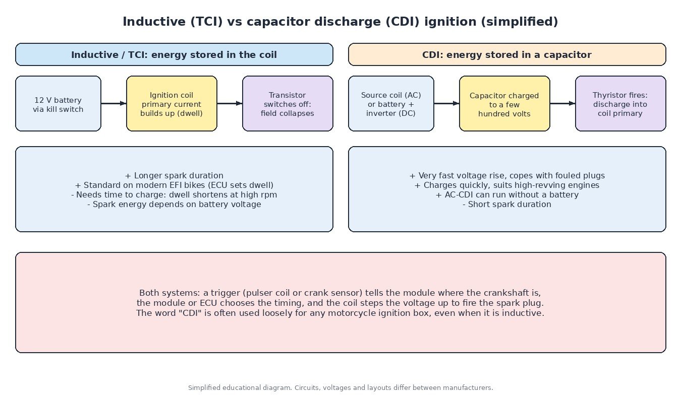
Battery or charging-system voltage is far too low to jump the gap of a spark plug under compression. The ignition coil is a transformer: a primary winding with few turns and a secondary winding with many more turns. A fast change of current in the primary induces a high voltage in the secondary, which breaks down the gap and starts combustion. The two main families differ in where the energy is stored before the spark and how quickly it is released.
Inductive ignition (TCI)
In a transistorised coil ignition, current flows through the coil primary for a period called dwell. During that time a magnetic field builds up and stores energy in the coil itself. At the firing point a transistor cuts the primary current, the field collapses and the secondary produces the high voltage. This is the same principle as the old contact-breaker (points) ignition, with a transistor replacing the points.
Inductive ignition gives a comparatively long spark duration, which helps light lean or poorly mixed charges. Its weakness is time: the coil needs a certain dwell to charge, and at very high engine speed there is less time available between sparks. Spark energy also depends on supply voltage, so a weak battery or poor ground weakens it. Modern ECUs manage this by controlling dwell against battery voltage and rpm, as explained in our article on ignition coils and dwell control.
Capacitor discharge ignition (CDI)
A CDI stores energy in a capacitor instead of the coil. The capacitor is charged to a few hundred volts, then at the firing point a thyristor (SCR) switches and dumps that charge into the coil primary. The coil works as a pulse transformer and the secondary voltage rises extremely quickly.
- AC-CDI charges the capacitor from a dedicated source (exciter) coil on the flywheel magneto. It needs no battery, which is why it is common on off-road bikes, older two-strokes, many small engines and some outboards.
- DC-CDI is powered from the 12 V battery through a small inverter inside the unit that raises the voltage to charge the capacitor. Because it does not depend on magneto output, the spark is more consistent at low cranking speed.
The fast rise time makes CDI good at firing slightly fouled plugs, which suited oily two-stroke engines, and the capacitor recharges quickly, so it copes well with high rpm. The trade-off is a very short spark duration.
How the module knows when to fire
Most simple systems use a pulser coil (pickup) next to the flywheel or rotor. A raised tab or reluctor passes the pulser and induces a small voltage pulse. The amplitude of that pulse rises with engine speed, but its position relative to top dead centre is fixed by the mechanical layout.
Older analogue CDIs used the pulse shape and simple circuitry to give a limited advance. Digital CDIs measure the time between pulses to calculate rpm and then look up an advance curve stored in a microcontroller. Many also read a throttle position sensor, apply a rev limiter and sometimes offer selectable curves. On fuel-injected bikes, a crankshaft position sensor with a toothed wheel feeds the ECU, which controls fuel and ignition together; see how crank and cam sensors work.

Why modern bikes use the ECU and inductive coils
Emission rules and onboard diagnostics pushed manufacturers towards engine management that controls ignition and injection in one unit. Most current fuel-injected motorcycles use inductive stick coils or coil packs, with dwell and timing set by the ECU from ignition timing maps. Twins often use wasted-spark coils that fire two plugs at once, one of them on the exhaust stroke. Riders and parts sellers still call the module a “CDI”, so always check what the system really is before ordering parts.
Common faults
- Safety circuits: kill switch, side stand, neutral, clutch and tip-over switches can block ignition. See our guide to motorcycle start and run interlocks.
- Plug caps and HT leads: cracked caps, water ingress and corroded terminals cause misfires that look like module faults.
- Pulser or source coil: heat and vibration damage windings; a fault may show only when hot.
- Grounds and connectors: corrosion on the module or coil ground is a classic cause of weak or missing spark.
- Charging problems on DC systems: a failing regulator/rectifier or stator starves the ignition.
- Sheared flywheel key: the rotor moves on the crank and timing is wrong, even with healthy electronics.
Diagnosing no spark
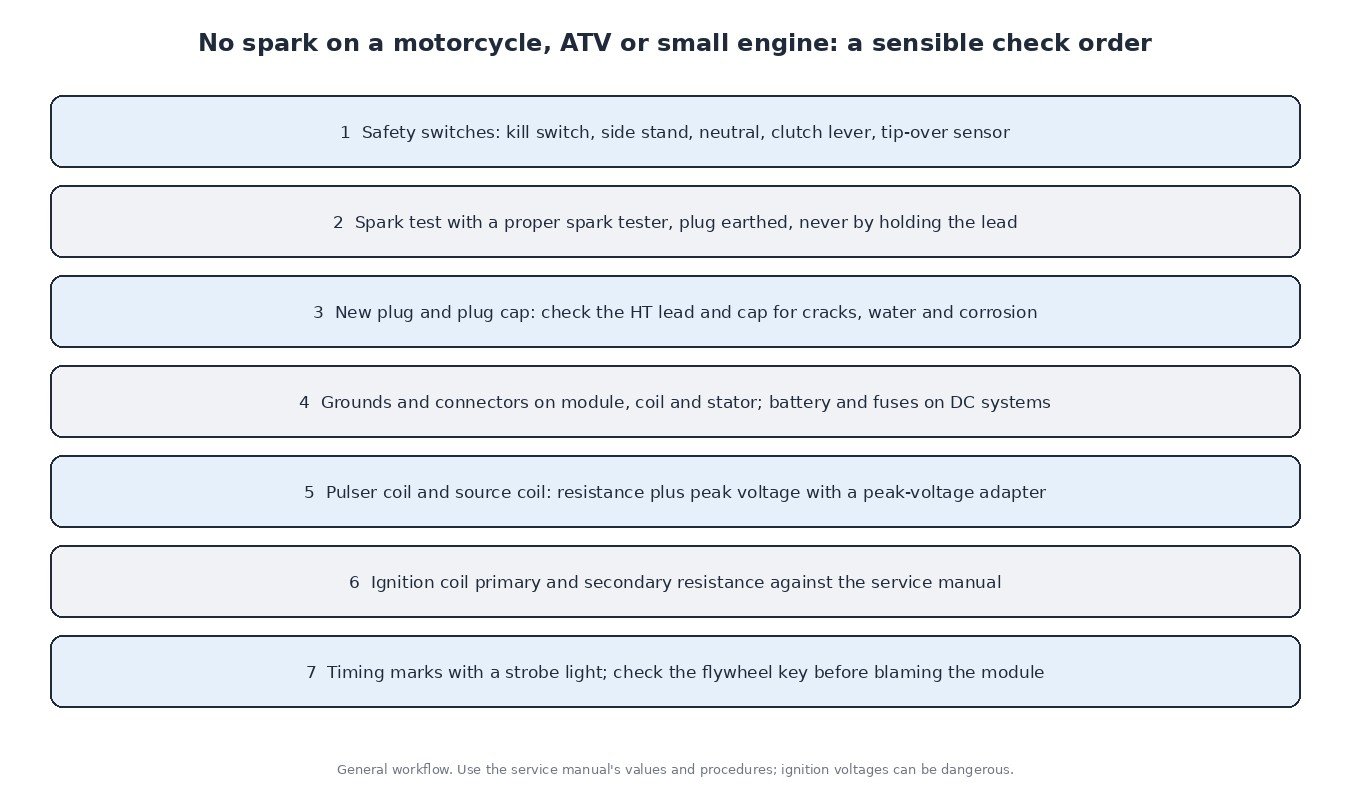
Work from simple to complex. Check the safety switches and fuses first, then test spark with a proper spark tester and a good plug, never by holding the lead. Inspect caps, leads and every ground. Measure pulser and source coil resistance against the service manual, but remember a resistance check does not prove output. CDI outputs and pulser signals are short pulses, so a normal multimeter cannot read them correctly; the manuals specify a peak voltage adapter for these tests. Check coil primary and secondary resistance, then confirm timing with a strobe light against the marks. Only replace the CDI or ECU once everything around it is proven good.
Ignition and tuning
On carburettor bikes, ignition changes usually mean an aftermarket programmable module with a different advance curve or rev limit. On fuel-injected bikes, timing lives in the ECU calibration together with fuel, throttle and limiter maps. More advance is not automatically more power: beyond the best point it adds heat and knock risk. Fix ignition faults first and start from an original read of your ECU.
Related fault codes (DTCs)
Carburettor bikes with a simple CDI usually store no codes at all. Fuel-injected models, especially newer ones with Euro 5 OBD, may report generic codes like these, while many brands also use their own codes or blink patterns.
| Code | Meaning | Typical causes |
|---|---|---|
| P0335 | Crankshaft position sensor “A” circuit | Faulty crank or pulser sensor, open or shorted wiring, corroded connector, damaged reluctor teeth or tabs |
| P0336 | Crankshaft position sensor “A” circuit range/performance | Wrong air gap, damaged or dirty reluctor, intermittent wiring, electrical interference from HT leads |
| P0320 | Ignition/distributor engine speed input circuit | Missing or erratic engine speed signal, trigger sensor or wiring fault, poor grounds |
| P0322 | Ignition/distributor engine speed input circuit no signal | Open circuit to the trigger sensor, failed sensor, disconnected or water-damaged connector |
| P0351 | Ignition coil “A” primary/secondary circuit | Failed coil, open primary winding, wiring or connector fault, faulty driver in the ECU or ignition module |
| P0352 | Ignition coil “B” primary/secondary circuit | Same causes as P0351 on the second coil, often on twins and wasted-spark systems |
| P0300 | Random/multiple cylinder misfire detected | Weak spark, worn plugs, cracked caps or leads, low system voltage, fuel delivery or air leaks |
| P0301 | Cylinder 1 misfire detected | Plug, cap, lead or coil fault on cylinder 1, injector problem, low compression |
| P0302 | Cylinder 2 misfire detected | Plug, cap, lead or coil fault on cylinder 2, injector problem, low compression |
| P0562 | System voltage low | Weak battery, faulty regulator/rectifier or stator, poor main ground, high resistance in the supply |
| P0563 | System voltage high | Faulty regulator/rectifier, poor regulator ground, wrong battery type |
Generic SAE meanings shown. Manufacturer codes, test values and procedures vary, so check the service manual for your model.
Ignition healthy and ready for a calibration? Upload your original ECU read to ECUFileMarket and get a file built for your exact ECU software.