
With fixed cam timing, valve events are a compromise: good at one engine speed, weaker everywhere else. Variable valve timing (VVT), or cam phasing, lets a hydraulic phaser rotate the camshaft earlier or later while the engine runs, with the engine control unit (ECU) deciding the angle. Here is how the hardware works, how the ECU closes the loop, why oil matters so much, and how to diagnose the common codes.
The parts of a cam phasing system
- Cam phaser – usually a vane type. The housing is part of the crank-driven sprocket; a vaned rotor inside is bolted to the camshaft. Each vane separates an advance chamber from a retard chamber.
- Oil control valve (OCV) – the VVT solenoid. It moves a spool that sends pressurised oil to the advance or retard chambers while the other side drains.
- Oil supply – pump oil passes the filter and often a small screen, then reaches the phaser through the cam bearing or central bolt.
- Camshaft position (CMP) sensor – compared with the crankshaft (CKP) signal, it gives the ECU the actual cam angle.
- Lock pin and springs – a spring-loaded pin usually locks the phaser at its base position at start-up until oil pressure builds; many exhaust phasers add a return spring.
Why the ECU moves the camshaft
Phasing shifts when the valves open and close and how much valve overlap there is around top dead centre. Strategies vary by engine, but typically:
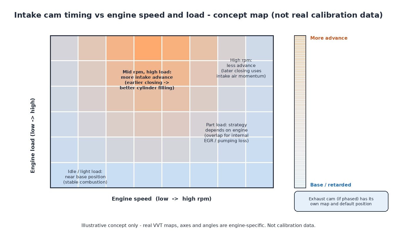
- Idle and very light load – the cam stays near its base position for stable combustion.
- Mid-range at high load – advancing the intake cam closes the intake valve earlier, trapping more air and lifting torque.
- High rpm – less advance, so later closing uses the momentum of the incoming air.
- Part load – extra overlap or late intake closing cuts pumping losses and adds internal exhaust gas recirculation.
- Turbo petrol at low rpm – controlled overlap lets fresh air scavenge through to the turbine, so boost builds sooner.
Closed-loop control inside the ECU
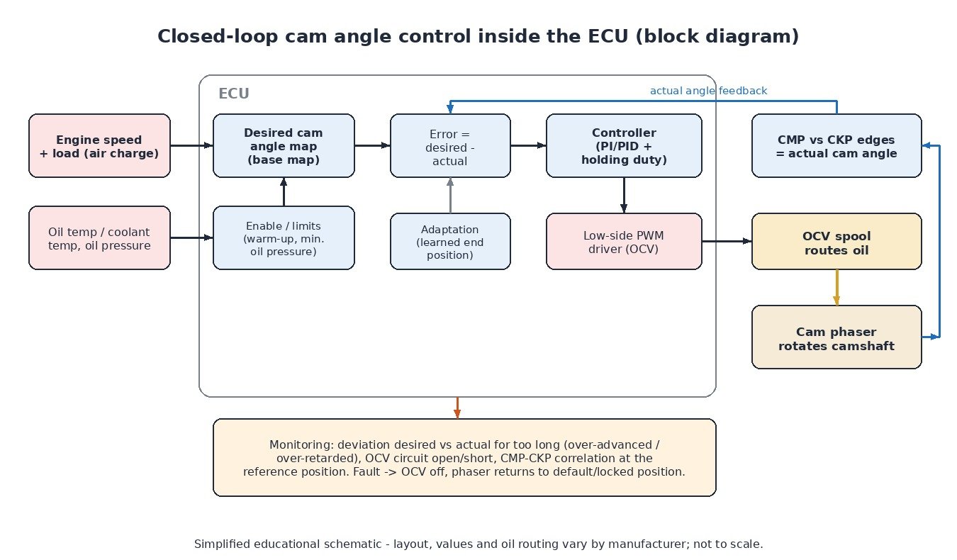
The ECU looks up a desired cam angle in base maps over engine speed and load, separately for intake and exhaust where both are phased. Enable conditions for temperature and oil pressure apply; many engines keep the phaser locked until oil is warm or rpm is high enough.
The ECU then compares the desired angle with the actual angle measured from the CMP and CKP signals. A controller, typically PI or PID with a learned holding duty, adjusts the PWM signal to the OCV. More duty moves the spool one way, less moves it the other way, and a middle “hold” duty blocks both chambers so the phaser stays where it is. The base map gives the target; cam sensor feedback makes sure it is reached. Most systems also learn a reference position to compensate for tolerances in the timing drive.
Why oil is part of the control system
The phaser is a hydraulic actuator, so its speed and accuracy depend on the oil. Low level, wrong viscosity, overdue changes, sludge or a blocked screen slow the response or let the phaser drift. Very hot, thin oil leaks past the vanes; cold, thick oil makes the phaser sluggish. Many VVT faults appear after a service with the wrong grade, so use the manufacturer-approved specification.
Symptoms of VVT problems
Typical signs are a warning lamp with cam timing codes, rough warm idle, flat mid-range torque, a short rattle on cold start (lock pin or worn phaser), higher fuel consumption and sometimes reduced power.
Step-by-step diagnostics
- Check oil level, grade and service history first.
- Read codes and freeze frame. Separate electrical (circuit), performance (over-advanced/retarded) and crank–cam correlation faults.
- Compare desired and actual cam angle in live data. Snap the throttle and watch whether the actual value follows the target and how quickly.
- Run the actuator test if available; idle should change when the OCV is commanded.
- Test and inspect the OCV. Check coil resistance against the service value, scope the PWM signal, look for oil in the connector, and check the spool and screens for debris.
- Verify mechanical timing. Correlation codes such as P0016 often point to a stretched chain, worn guides, a jumped tooth or a phaser not returning to its lock position. Check the timing marks or use the manufacturer’s cam/crank deviation data.
Cars, vans, trucks, tractors and motorcycles
Intake phasing, often with exhaust phasing too, is standard on most modern petrol cars and vans. Petrol V6 and V8 engines in pickups and light trucks phase each bank separately, so Bank 2 codes apply. Diesels more often keep fixed timing, though some modern units use variable valve actuation, for example for exhaust heat management; most tractor and heavy-duty diesels have fixed main cam timing. Many sport and touring motorcycles combine cam phasing or variable lift with ride-by-wire throttles for smooth low-speed running and strong top-end power.
Related fault codes (DTCs)
Generic SAE J2012 codes. “A” is typically intake and “B” exhaust, but the manufacturer assigns them, so confirm with service data.
| Code | Meaning | Typical causes |
|---|---|---|
| P0010 | “A” Camshaft Position Actuator Circuit (Bank 1) | OCV coil open/short, wiring, connector |
| P0011 | “A” Camshaft Position – Timing Over-Advanced or System Performance (Bank 1) | Low or wrong oil, stuck OCV, clogged screen, sticking phaser |
| P0012 | “A” Camshaft Position – Timing Over-Retarded (Bank 1) | OCV stuck, low oil pressure, phaser stuck at lock position |
| P0013 | “B” Camshaft Position Actuator Circuit (Bank 1) | Exhaust OCV circuit, wiring, connector |
| P0014 / P0015 | “B” Camshaft Position – Timing Over-Advanced or System Performance / Over-Retarded (Bank 1) | Oil, OCV, phaser, return spring |
| P0016 / P0017 | Crankshaft Position – Camshaft Position Correlation Bank 1 Sensor A / B | Stretched chain, jumped tooth, CMP fault, phaser not locked |
| P0018 / P0019 | Crankshaft Position – Camshaft Position Correlation Bank 2 Sensor A / B | As P0016/P0017 |
| P0020 / P0023 | “A” / “B” Camshaft Position Actuator Circuit (Bank 2) | OCV circuit on Bank 2 |
| P0021 / P0022 | “A” Camshaft Position – Timing Over-Advanced or System Performance / Over-Retarded (Bank 2) | Oil, OCV, phaser on Bank 2 |
| P0024 / P0025 | “B” Camshaft Position – Timing Over-Advanced or System Performance / Over-Retarded (Bank 2) | Oil, exhaust OCV, phaser on Bank 2 |
| P0026 / P0027 | Intake / Exhaust Valve Control Solenoid Circuit Range/Performance (Bank 1) | Sticking solenoid, contamination, intermittent wiring |
| P0075 / P0076 / P0077 | Intake Valve Control Solenoid Circuit / Low / High (Bank 1) | Open circuit, short to ground or voltage, failed solenoid |
| P0078 / P0079 / P0080 | Exhaust Valve Control Solenoid Circuit / Low / High (Bank 1) | Open circuit, short to ground or voltage, failed solenoid |
What it means for tuning
Cam target maps are part of a petrol calibration and are often adjusted alongside boost, ignition and fuelling, because cam timing affects air charge, knock margin, exhaust temperature and turbo response. Changes must be verified with logged desired versus actual cam angle. A remap cannot fix a worn chain, sticking phaser or bad oil, and cam monitoring should never be disabled to hide a mechanical fault: repair first, then calibrate.
Looking for a calibration that keeps cam timing within safe, monitored limits? Browse the tuning file catalogue at ECUFileMarket.