
Almost every modern diesel, from a 1.6-litre hatchback to a 13-litre truck engine and a 200 hp tractor, breathes through a variable geometry turbocharger (VGT, also called VNT or VTG). It is the reason a small diesel pulls cleanly from low rpm and still makes power at the top end. For technicians it is also one of the most common sources of limp mode, boost faults and failed remaps. This article explains how a VGT works, how the ECU controls it, and what that means for diagnostics and calibration.
The problem a fixed turbo cannot solve
A turbocharger turns exhaust energy into intake pressure. The exhaust gas drives a turbine wheel, which spins a compressor wheel on the same shaft. The size of the turbine housing decides how the turbo behaves. A small housing accelerates the gas strongly, so the turbo spools quickly at low engine speed, but at high flow it becomes a restriction, raising exhaust backpressure and exhaust temperature. A large housing flows well at high rpm but responds slowly at low rpm, which the driver feels as turbo lag.
A classic fixed-geometry turbo solves part of this with a wastegate, a valve that lets exhaust bypass the turbine once the target pressure is reached. The wastegate limits boost, but it cannot make a big turbine respond like a small one.
How the variable vanes work
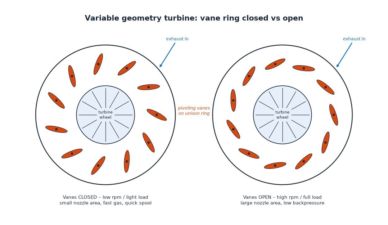
A VGT keeps one turbine wheel but surrounds it with a ring of small movable guide vanes. All vanes are linked to a unison ring, so they pivot together when an actuator moves a lever on the outside of the housing.
- Vanes closed (narrow passages): the exhaust is forced through a small opening, it speeds up and hits the turbine blades at a steeper angle. The turbo spins up quickly even with little exhaust flow, which gives strong low-rpm boost.
- Vanes open (wide passages): the flow area grows, backpressure drops and the turbine can handle high exhaust mass flow without choking the engine at high rpm.
In effect the turbo behaves like a small turbine at low load and a larger one at high load, which is why most VGTs need no wastegate at all. Because the vanes sit in the hot gas stream, VGTs are mainly found on diesels, where exhaust temperatures are lower than on petrol engines. Petrol applications exist but are rare and use special high-temperature materials.
Actuators: vacuum and electric
The vane position is set by an actuator, and there are two main families:
- Vacuum (pneumatic) actuators. A diaphragm can is fed vacuum from the engine’s vacuum pump through an electro-pneumatic valve. The ECU drives that valve with a PWM (pulse-width modulated) signal, so the duty cycle decides how much vacuum reaches the can and how far the vanes move.
- Electric actuators. A small DC motor with a gearbox and an internal position sensor moves the vanes directly. Depending on the system it is driven by a PWM signal or acts as a “smart” actuator on a CAN bus, reporting its position and fault status back to the ECU. Electric actuators are faster and more precise and are standard on most current car and heavy-duty engines.
How the ECU controls boost
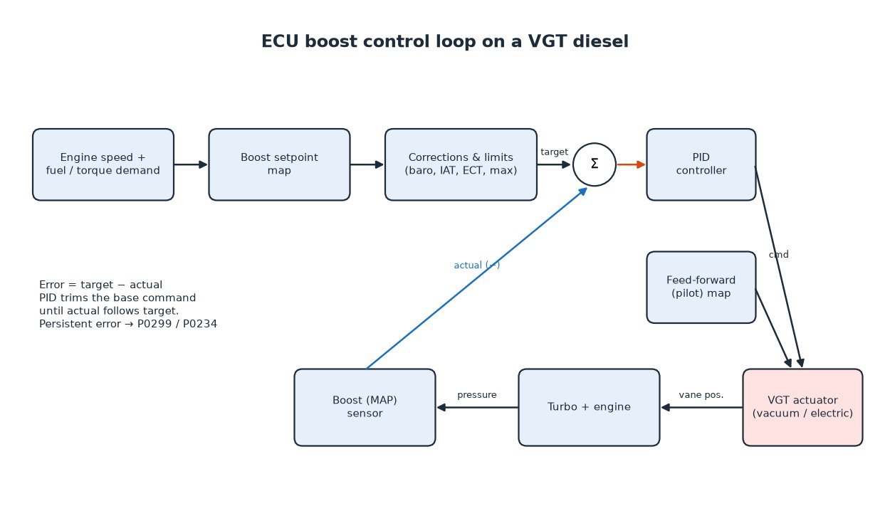
Boost control on a VGT diesel is normally a closed-loop system built from a few blocks that you will recognise in most calibrations:
- Boost setpoint. The ECU calculates a target intake manifold pressure, usually from engine speed and injected fuel quantity or requested torque.
- Corrections and limits. The setpoint is adjusted for ambient (atmospheric) pressure, intake air temperature and coolant temperature, and capped by a maximum boost limit. The ambient pressure correction protects the turbo from overspeeding at altitude, where it has to work at a higher pressure ratio to reach the same absolute boost.
- Pilot (feed-forward) control. A base actuator position or duty cycle is taken from a map, so the vanes are already close to the right position before the controller corrects anything.
- Closed-loop correction. A PID-type controller compares the setpoint with the actual pressure from the boost (MAP) sensor and trims the actuator command to remove the error.
On many engines the VGT has other jobs too. Closing the vanes raises exhaust backpressure, which helps drive exhaust gas recirculation, speeds up warm-up and supports DPF regeneration strategies. On heavy-duty engines the VGT is often also used as part of the engine brake, closing hard on overrun to create retarding torque.
Typical faults and how to diagnose them
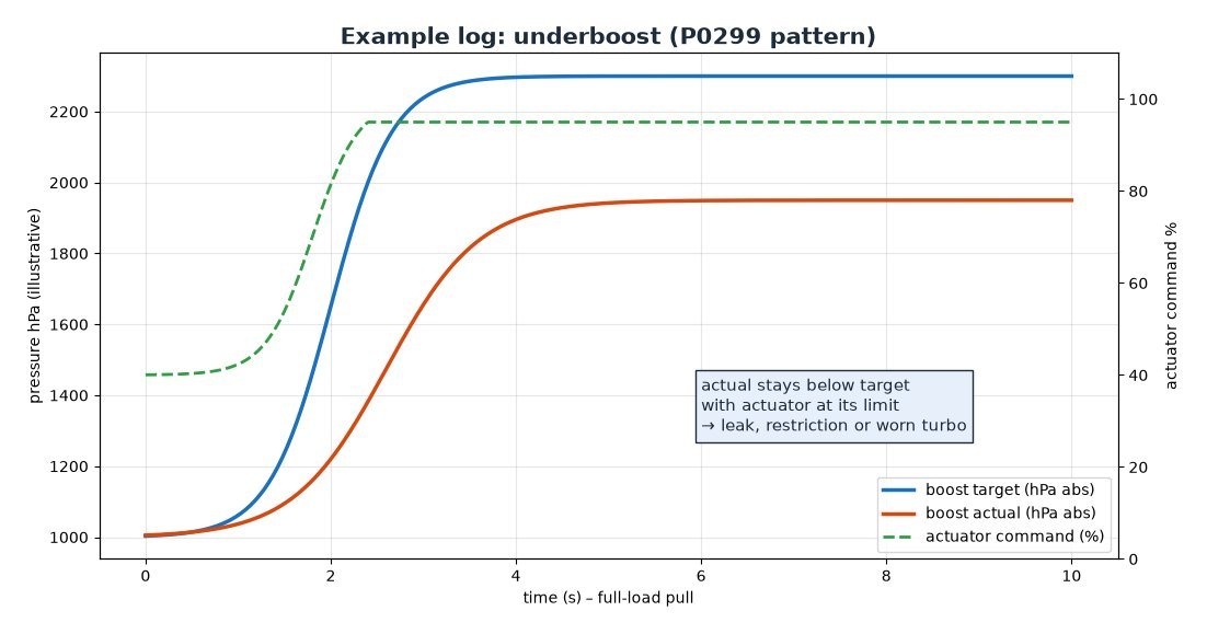
The two classic codes are P0299 (underboost) and P0234 (overboost). They tell you the actual pressure did not follow the setpoint, not why. A structured check saves a lot of parts:
- Read live data first. Log boost setpoint, actual boost and actuator command or position during a full-load pull in a suitable gear. Underboost with the actuator already at its limit points to a leak or a mechanical problem; a lagging or oscillating actual value points to sticking vanes or poor control.
- Check for leaks. Split intercooler hoses and loose clamps are the most common cause of underboost. A smoke test of the intake side is quick and conclusive.
- Check the actuator path. On vacuum systems, test the vacuum supply, the hoses and the control valve. On electric actuators, read their own fault codes and perform the end-stop or position learn routine with a diagnostic tool after replacement where the manufacturer requires it.
- Look for sticking vanes. Short-trip driving and heavy soot loading can make the vane mechanism stiff, especially if it rarely reaches full travel. A vane that sticks closed often causes overboost on a sudden load change.
- Verify the sensors. A drifting MAP or ambient pressure sensor makes the controller chase the wrong value. With the engine off, both should read close to the same atmospheric pressure.
Related fault codes (DTCs)
These are the generic OBD-II (SAE J2012) codes most often linked to VGT and boost control faults. Exact wording and enable conditions vary by manufacturer, so always confirm against the vehicle's own fault-code description and live data.
| Code | Meaning | Typical causes |
|---|---|---|
| P0045 | Turbocharger/Supercharger Boost Control "A" Circuit/Open | Open circuit or unplugged connector at the VGT actuator or boost pressure control (vacuum converter) valve, damaged wiring, failed solenoid/actuator |
| P0046 | Turbocharger/Supercharger Boost Control "A" Circuit Range/Performance | Actuator or control valve not responding as commanded, sticking vanes, vacuum supply problem, high-resistance wiring |
| P0047 | Turbocharger/Supercharger Boost Control "A" Circuit Low | Control circuit shorted to ground, failed control valve or actuator |
| P0048 | Turbocharger/Supercharger Boost Control "A" Circuit High | Control circuit shorted to voltage or open ground, failed control valve or actuator |
| P0049 | Turbocharger/Supercharger Turbine Overspeed | Vanes stuck closed, overboost, incorrect calibration (e.g. altitude correction removed), boost sensor reading low |
| P0069 | Manifold Absolute Pressure – Barometric Pressure Correlation | MAP/boost sensor or barometric sensor drift, blocked sensor port, wiring fault (sensors disagree with engine off) |
| P0106 | Manifold Absolute Pressure/Barometric Pressure Circuit Range/Performance | Contaminated or faulty MAP sensor, leaking sensor hose or port, boost leaks |
| P0107 | Manifold Absolute Pressure/Barometric Pressure Circuit Low | Open/short to ground in signal or 5 V reference, failed sensor |
| P0108 | Manifold Absolute Pressure/Barometric Pressure Circuit High | Signal shorted to voltage, open ground, failed sensor |
| P0234 | Turbocharger/Supercharger "A" Overboost Condition | Vanes sticking closed (carbon), slow or faulty actuator, vacuum control valve fault, boost sensor error, aggressive calibration |
| P0235 | Turbocharger/Supercharger Boost Sensor "A" Circuit | Boost pressure sensor or wiring fault |
| P0236 | Turbocharger/Supercharger Boost Sensor "A" Circuit Range/Performance | Implausible boost sensor reading: sensor drift, blocked or leaking sensor connection, charge-air leak |
| P0237 | Turbocharger/Supercharger Boost Sensor "A" Circuit Low | Signal circuit open or shorted to ground, failed sensor |
| P0238 | Turbocharger/Supercharger Boost Sensor "A" Circuit High | Signal shorted to voltage, open ground, failed sensor |
| P0299 | Turbocharger/Supercharger "A" Underboost Condition | Charge-air leaks (hoses, intercooler, clamps), vanes stuck open, actuator/vacuum fault, restricted intake or exhaust (DPF), worn turbo |
| P2263 | Turbocharger/Supercharger Boost System Performance | Boost leaks, sticking vanes, actuator fault, restricted exhaust, sensor errors |
| P2562 | Turbocharger Boost Control Position Sensor "A" Circuit | VGT position sensor (often inside the actuator) or wiring fault |
| P2563 | Turbocharger Boost Control Position Sensor "A" Circuit Range/Performance | Position does not match command: sticking vanes or linkage, actuator needs adaptation/learn, failed position sensor |
| P2564 | Turbocharger Boost Control Position Sensor "A" Circuit Low | Signal open or shorted to ground, failed position sensor |
| P2565 | Turbocharger Boost Control Position Sensor "A" Circuit High | Signal shorted to voltage or open ground, failed position sensor |
| P2566 | Turbocharger Boost Control Position Sensor "A" Circuit Intermittent | Loose or corroded connector, chafed harness near the hot turbo |
What it means for calibration
When a VGT engine is tuned, boost is never just “turned up”. A professional file adjusts the setpoint, the limiters and the pilot control together, and keeps the turbo inside its safe operating area for pressure ratio, shaft speed and exhaust temperature, including at altitude. The smoke limiter, which caps fuel based on measured air mass, must match the new airflow, otherwise the engine either smokes or loses the gain. Raising only the maximum boost limit while leaving the rest of the boost control untouched is a common cause of overboost faults and limp mode after a cheap remap. And most importantly: if the car is already underboosting on the stock file, fix the hardware before any tuning.
Key takeaway
A VGT changes the turbine’s effective size by moving its guide vanes, and the ECU positions those vanes in a closed loop to hit a boost target that is corrected for conditions and limited for protection. Understanding that loop is the fastest way to diagnose boost faults and the basis of every safe diesel calibration.
Need a professionally calibrated file for a VGT diesel car, truck or tractor? Order your tuning file from ECUFileMarket.