
Petrol direct injection, sold under names such as GDI, TSI, TFSI or FSI depending on the manufacturer, moved the injector from the intake port into the combustion chamber itself. That single change brought better efficiency, more torque and more precise control, but it also required a completely different fuel system: a low-pressure supply, a mechanically driven high-pressure pump, a pressurised rail and injectors that open against cylinder pressure in fractions of a millisecond. This guide explains how each part works, how the ECU keeps rail pressure on target, what goes wrong, and what it all means when an engine is recalibrated.
The two pressure stages
Low-pressure supply in the tank
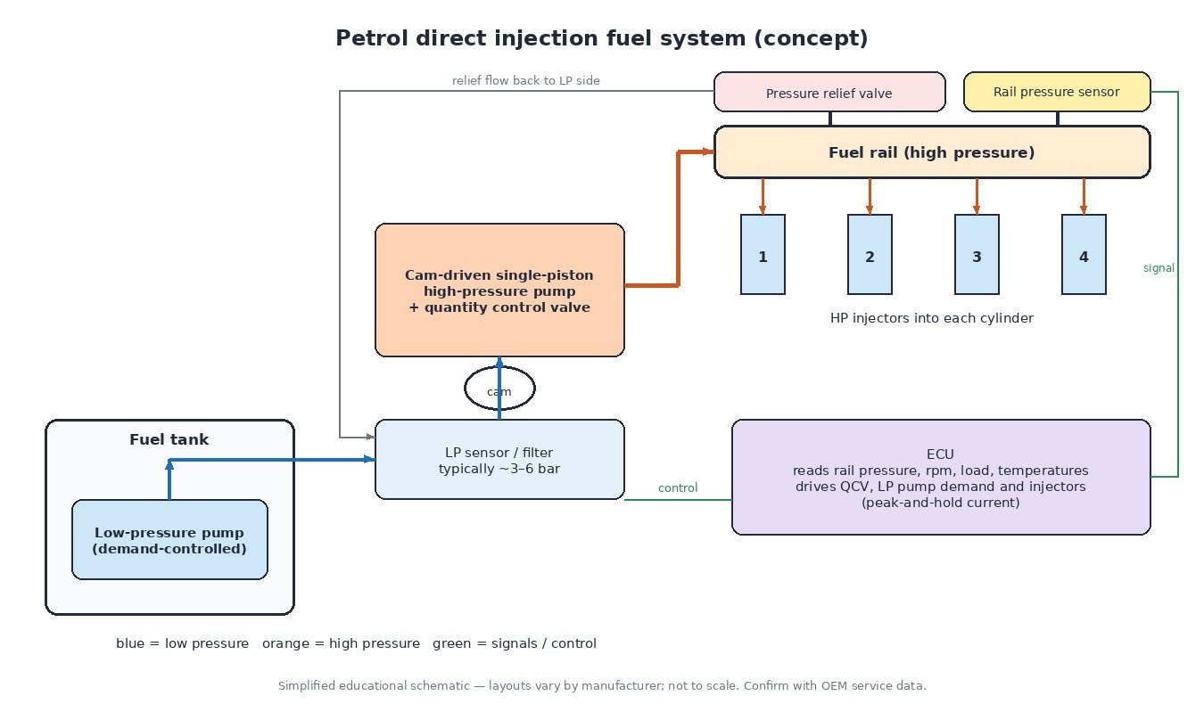
An electric pump in the tank feeds fuel to the engine bay at a few bar, typically somewhere around 3 to 6 bar. On most modern systems this pump is demand-controlled: a pump control module or the ECU varies its speed using a low-pressure sensor, so the pump delivers only what the engine needs instead of running flat out and returning the excess. This saves energy and limits fuel heating.
The cam-driven high-pressure pump
The high-pressure pump is usually a single-piston unit driven by extra lobes on a camshaft, often three or four. Each lobe gives one pumping stroke. A solenoid-operated quantity control valve (also called a fuel pressure regulator or metering valve) sits at the pump inlet. During the delivery stroke the valve stays open at first and excess fuel is pushed back to the low-pressure side. When the ECU closes the valve, the remaining stroke is pressurised and delivered to the rail. Closing earlier delivers more fuel; closing later delivers less. A damper on the low-pressure side smooths the pulses this creates.
Rail, sensor and pressure relief
The rail stores fuel at high pressure and distributes it to each injector. Typical operating pressures on petrol direct injection have historically been around 100 to 200 bar, with newer engines often running higher. A rail pressure sensor reports the actual value to the ECU, and a mechanical pressure relief valve, either in the rail or in the pump, opens if pressure ever exceeds a safe limit and sends fuel back to the low-pressure side.
High-pressure injectors and peak-and-hold drive
Most petrol DI engines use multi-hole solenoid injectors; some use outward-opening piezo injectors. Because the needle must open quickly against high rail pressure, the ECU drives solenoid injectors with a peak-and-hold strategy. A boost voltage of several tens of volts, stored in the ECU’s output stage, pushes a high current through the coil to open the needle fast. The current is then reduced to a lower hold level for the rest of the injection. This gives fast, repeatable opening without overheating the coil or the driver. Piezo injectors use a dedicated high-voltage charge and discharge profile instead.
Closed-loop rail pressure control
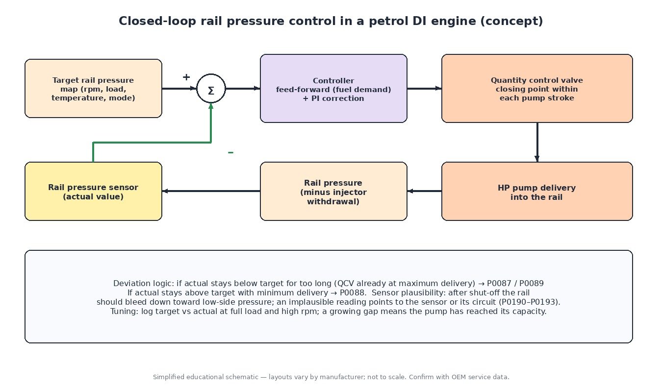
The ECU picks a target rail pressure from maps based on engine speed, load, temperature and operating mode. Higher pressure gives finer atomisation and shorter injection times at high load; lower pressure at idle helps metering accuracy and reduces pump work. A feed-forward value based on the fuel quantity being injected sets the basic valve timing, and a closed-loop correction trims it using the rail pressure sensor. The deviation between target and actual is monitored continuously, which is what drives the pressure-related fault codes.
Split and multiple injections
Injecting directly into the cylinder lets the ECU choose when fuel arrives. Most engines inject during the intake stroke for a homogeneous mixture, but many also use two or more injections per cycle. Typical uses are catalyst heating after a cold start (a late injection combined with retarded ignition), reducing knock at high load, and cutting particulate emissions by avoiding fuel wetting the piston and cylinder walls. Early direct-injection designs also used stratified lean operation, injecting late in the compression stroke.
Carbon build-up on intake valves
With port injection, fuel sprays onto the back of the intake valves and keeps them clean. With direct injection that washing effect is gone, so oil vapour from crankcase ventilation and exhaust gas residues can bake onto the valves over time. Heavy deposits disturb airflow, causing rough idle, misfires and lean codes. Cleaning is usually done by media blasting with the intake removed. This is one reason several manufacturers now fit dual injection: port injectors for light load and cleaner valves, plus direct injectors for high load and knock resistance, with the ECU blending the two.
How it differs from diesel common rail
Diesel common-rail systems run at far higher pressures and use a continuously driven pump, often with a separate rail pressure control valve, and their servo-hydraulic injectors have a back-leak return. In a diesel, injection timing also sets the start of combustion, while a petrol engine relies on the spark. For the diesel side, see our guide on how common-rail diesel rail pressure control works. On motorcycles and small engines, port injection is still the norm; direct injection appears mainly on some two-stroke engines, often with simpler, lower-pressure systems.
Related fault codes (DTCs)
| Code | Meaning | Typical causes |
|---|---|---|
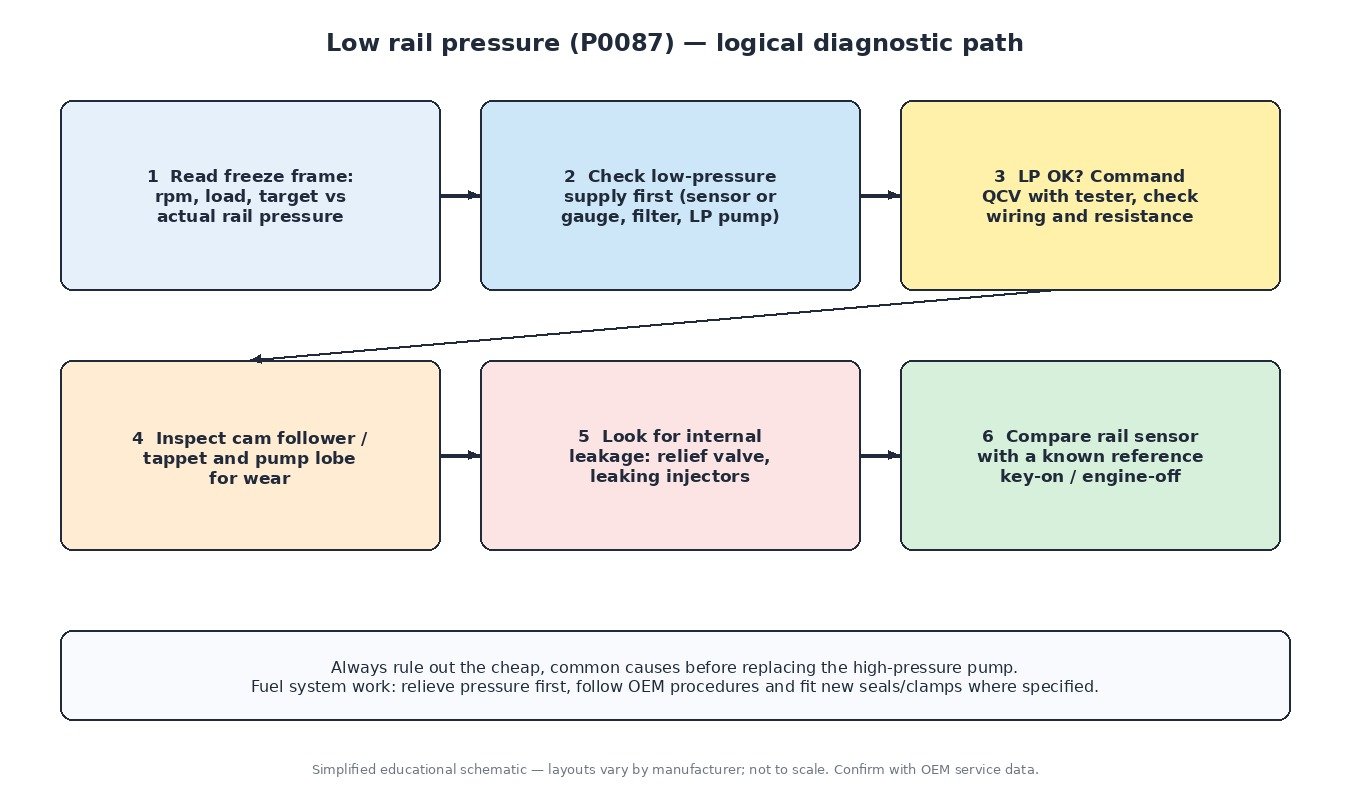
| P0087 | Fuel Rail/System Pressure Too Low | Weak low-pressure supply, blocked filter, worn HP pump or cam follower, quantity control valve fault, leaking relief valve or injectors |
| P0088 | Fuel Rail/System Pressure Too High | Quantity control valve stuck, relief valve fault, wiring or rail pressure sensor error |
| P0089 | Fuel Pressure Regulator 1 Performance | Control valve sticking, pump wear, poor low-pressure feed |
| P0090 / P0091 / P0092 | Fuel Pressure Regulator 1 Control Circuit / Low / High | Open or shorted valve coil, damaged connector, wiring fault, ECU driver |
| P0190 / P0191 | Fuel Rail Pressure Sensor “A” Circuit / Range/Performance | Sensor drift, implausible reading against the reference, wiring or 5 V supply issue |
| P0192 / P0193 | Fuel Rail Pressure Sensor “A” Circuit Low / High | Short to ground or supply, open signal circuit, failed sensor |
| P0201–P0204 | Injector Circuit/Open – Cylinder 1–4 | Injector coil open, wiring or connector damage, ECU output stage |
| P0171 / P0174 | System Too Lean Bank 1 / Bank 2 | Low fuel pressure, air leaks, intake valve deposits, MAF error |
| P0300 | Random/Multiple Cylinder Misfire Detected | Low rail pressure, carbon build-up, leaking injectors, ignition faults |
| P0627 | Fuel Pump “A” Control Circuit/Open | Pump control module, wiring, connector, pump motor |
What it means for tuning
More torque means more fuel per cycle, and the high-pressure pump can only deliver so much per stroke. At high load and engine speed, a stock pump can reach its limit and actual rail pressure starts falling below target. Logging target versus actual rail pressure and the control valve demand is the clearest way to see this. Raising the pressure target can help atomisation but brings the pump and relief valve closer to their limits, and at high rpm the available injection window becomes short, so injection timing must be chosen carefully to avoid wall wetting, oil dilution and smoke. That is why a good calibration treats the fuel system as a whole rather than simply adding boost.
Need an engineered tuning file for your petrol DI engine? Upload your original read at ECUFileMarket.