
A quickshifter lets a rider change up a gear with the throttle held open and without touching the clutch. It feels like magic the first time, but it is really a short, carefully timed torque interruption controlled by the engine ECU. Many current sport and touring motorcycles also add an auto-blipper, which does the opposite job on downshifts. This guide explains how both systems work, what the ECU calibration controls, how the same idea appears on cars, trucks and tractors, and how to diagnose a quickshifter that misbehaves.
Why a gearbox needs a torque break
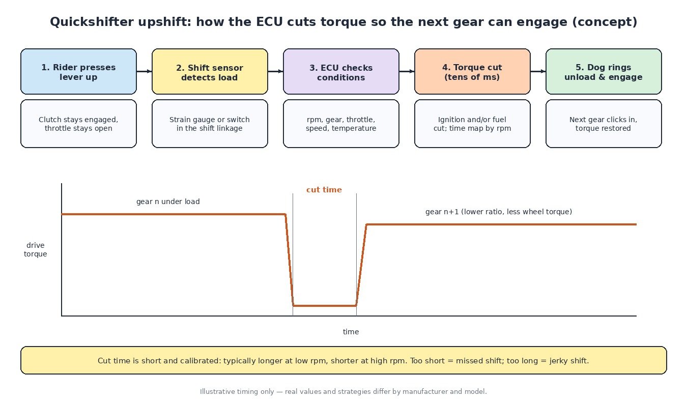
Most motorcycle gearboxes are sequential, constant-mesh designs. The gears are always meshed, and a gear is selected by sliding dog rings or dog gears sideways so their dogs lock into the neighbouring gear. While the engine is driving hard, the dogs are pressed together under load and the shift fork cannot slide them apart. Pulling the clutch or briefly closing the throttle removes that load. A quickshifter does the same thing electronically, without the rider changing grip or pulling the lever.
The shift sensor
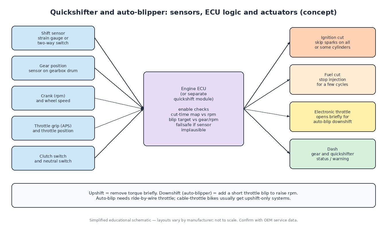
The input is a sensor in the gear linkage. Simple systems use a switch that closes when the lever travels far enough. Most modern systems use a strain-gauge or load-cell sensor in the shift rod that measures force, so the ECU sees the rider’s foot pressure building before the lever actually moves. Some units are two-way and sense both upshift and downshift force. Factory systems are usually calibrated with a zero or learn routine, and aftermarket sensors usually need a threshold setting.
What the ECU does on an upshift
- The rider presses the lever up while accelerating.
- The sensor signal crosses its threshold.
- The ECU checks its enable conditions: engine speed above a minimum, a valid gear, throttle open enough, clutch not pulled, no relevant faults.
- It cuts torque for a calibrated time by suppressing ignition, fuel, or both, on all or some cylinders.
- With the dogs unloaded, the next gear engages and the ECU restores torque, often ramping it back in smoothly.
The cut time is the key calibration value. It is usually a map against engine speed and sometimes gear: longer at low rpm, where the gearbox turns more slowly, and shorter at high rpm. Too short and the gear may not engage, giving a missed shift or a false neutral. Too long and the bike surges or jerks when power comes back.
Auto-blipper: downshifts without the clutch
On a downshift the problem is reversed. The lower gear needs a higher engine speed, and an engine braking on the overrun loads the dogs the other way. An auto-blipper opens the electronic throttle briefly to raise rpm and unload the dogs so the lower gear can engage cleanly. The ECU decides how much throttle to add and for how long from target rpm, gear and road speed. This needs a ride-by-wire throttle, so bikes with a cable throttle usually get upshift-only systems. Slipper clutches and engine-braking control often work alongside the blipper to keep the rear wheel stable.
The same idea on other vehicles
Cars: sequential racing gearboxes use flat-shift and blip strategies very similar to bikes. Road cars with automatic and dual-clutch gearboxes use torque intervention requests over CAN, where the TCU asks the engine ECU to reduce torque during the shift. Trucks: automated manual transmissions request engine torque reduction and target engine speed to synchronise shifts, usually over J1939. Tractors: powershift gearboxes change under load with clutch packs, and the engine and transmission controllers coordinate torque during the change.
Diagnosing quickshifter faults
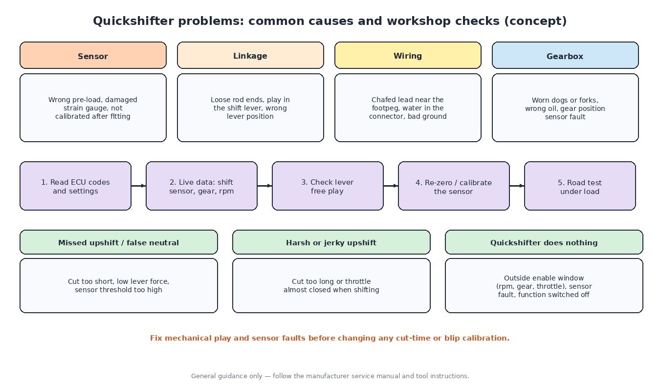
- Read the ECU for stored codes and check whether the function is enabled in the settings or riding mode.
- Watch the shift sensor value in live data while pressing the lever. It should rise cleanly and return to zero.
- Check rod ends and lever pivots for play. Slack in the linkage delays the signal and causes missed shifts.
- Re-zero or re-learn the sensor after fitting new parts or changing the lever position.
- Confirm the gear position sensor reads every gear correctly, because many systems disable themselves on an invalid gear.
- If shifts are still poor, check the gearbox itself: worn dogs, bent forks or the wrong oil will not be fixed by electronics.
What it means for calibration
On bikes with a factory quickshifter, cut times, enable windows and blip targets live in the ECU calibration. Adjusting them only makes sense after the mechanical side and the sensor are healthy, and changes are best checked with datalogs of rpm, gear and sensor force. Adding a quickshifter to a bike that was not built for it may need ECU support for the function as well as the hardware, and every change should start from a full original read of the ECU.
Related fault codes (DTCs)
Generic OBD-II codes (SAE J2012). Many motorcycles use manufacturer-specific codes or blink codes for the shift sensor and gear position sensor, so always check the service manual for the exact model.
| Code | Meaning | Typical causes |
|---|---|---|
| P0914 | Gear Shift Position Circuit | Open or shorted shift/gear sensor circuit, damaged connector, sensor failure |
| P0915 | Gear Shift Position Circuit Range/Performance | Signal outside the expected range: sensor not calibrated or zeroed, mechanical play, intermittent wiring |
| P0916 | Gear Shift Position Circuit Low | Short to ground, lost supply voltage, failed sensor |
| P0917 | Gear Shift Position Circuit High | Open signal or ground circuit, short to voltage |
| P0705 | Transmission Range Sensor “A” Circuit (PRNDL Input) | Gear/range position sensor or wiring fault, misadjusted sensor |
| P0706 | Transmission Range Sensor “A” Circuit Range/Performance | Sensor out of adjustment, worn sensor track, intermittent connection |
| P0335 | Crankshaft Position Sensor “A” Circuit | Failed crank sensor, wiring or connector fault: no rpm signal for shift logic |
| P0336 | Crankshaft Position Sensor “A” Circuit Range/Performance | Damaged trigger wheel, wrong air gap, electrical interference |
| P0500 | Vehicle Speed Sensor “A” | Failed speed sensor, wiring fault, damaged pulse ring |
| P0120 | Throttle/Pedal Position Sensor/Switch “A” Circuit | Throttle or grip position sensor or wiring fault |
| P0122 | Throttle/Pedal Position Sensor/Switch “A” Circuit Low | Short to ground, open supply, failed sensor |
| P0123 | Throttle/Pedal Position Sensor/Switch “A” Circuit High | Open ground, short to voltage, failed sensor |
| P2100 | Throttle Actuator “A” Control Motor Circuit/Open | Electronic throttle motor or wiring fault: auto-blip unavailable |
| P2101 | Throttle Actuator “A” Control Motor Circuit Range/Performance | Sticking throttle body, motor fault, poor connection |
| P0351 | Ignition Coil “A” Primary/Secondary Circuit | Coil or driver circuit fault; a weak coil can feel like a rough cut |
Closing
A quickshifter is a short torque cut triggered by a force sensor, and an auto-blipper is a short throttle opening. When either misbehaves, check the linkage, sensor zero and gear signal before touching the calibration.
Need a custom engineered ECU or TCU file built from your original read? Upload your file at ECUFileMarket.