
Carburettors ruled motorcycles for decades, but almost every modern road bike, many off-road models and most scooters now run electronic fuel injection (EFI). Bikes face problems cars rarely do: very short intakes, individual throttle bodies, high revs and big pulses in manifold pressure. This guide explains how motorcycle EFI measures engine load, how the ECU calculates fuel, and what that means for diagnostics and calibration work.
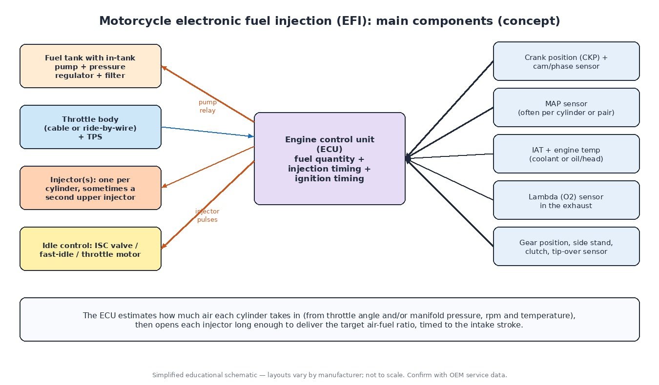
The main components
Fuel supply
Most current bikes use an electric pump inside the tank, often in one module with the filter and a pressure regulator, feeding a returnless line to the injectors. The ECU switches the pump through a relay, primes it for a few seconds at key-on and stops it if the engine does not turn or the tip-over (bank angle) sensor trips. Fuel pressure is fixed by the regulator, so the ECU controls quantity only through injector opening time.
Throttle bodies and injectors
Singles and many twins have one throttle body; sporty multi-cylinder bikes usually have one throttle per cylinder, each with its own injector. Some high-performance engines add a second, upstream injector that joins in at high rpm and load for better atomisation and charge cooling. The throttle is either cable-operated or ride-by-wire, where an electric motor sets the angle the ECU chooses from the twistgrip sensor. Either way a throttle position sensor (TPS) reports the angle.
Sensors
The ECU reads crankshaft position (and on many engines a cam or phase sensor), manifold pressure (MAP), intake air temperature (IAT), engine temperature (coolant, or oil/cylinder head on air-cooled engines), a lambda sensor in the exhaust, and switches such as gear position, side stand and clutch. Our MAP sensor guide covers the sensor itself in detail.
How the ECU measures engine load
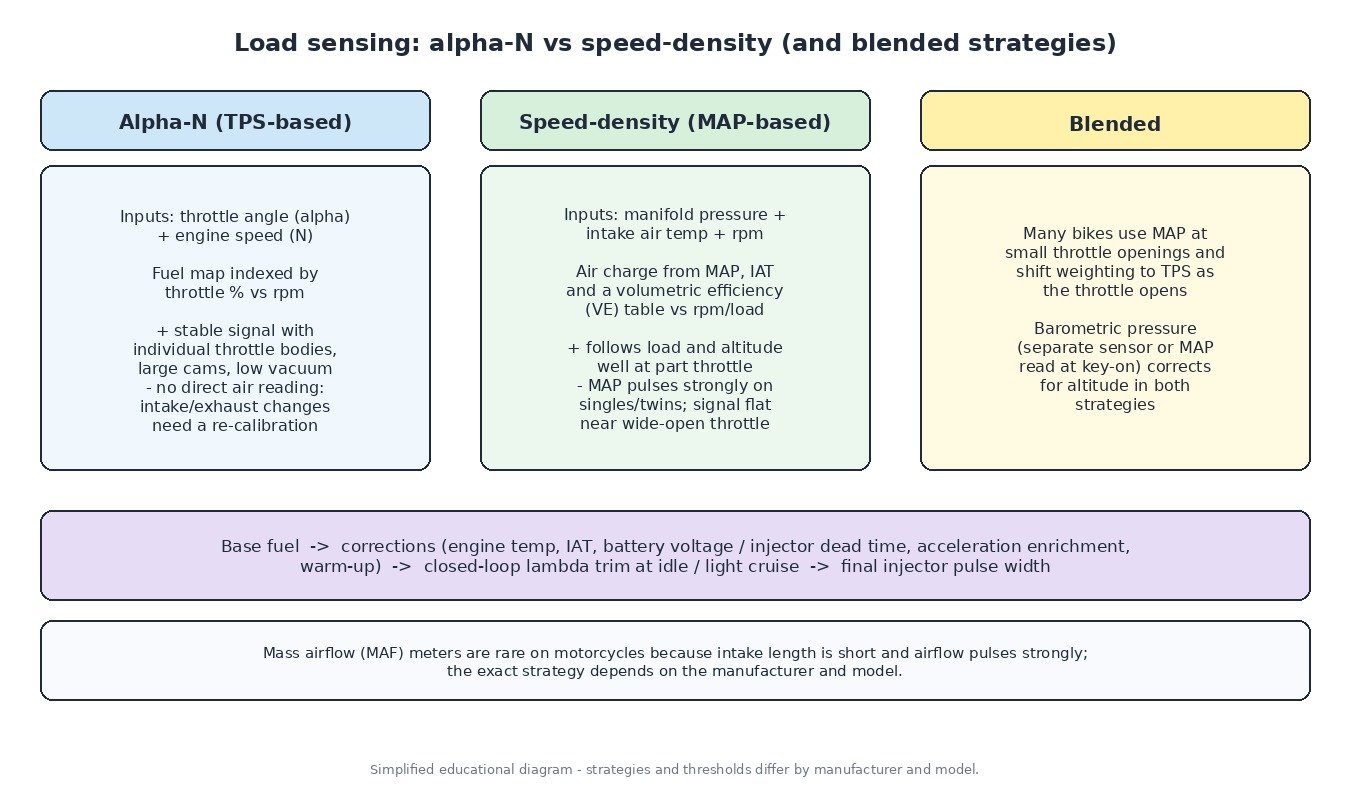
Fuel must match the mass of air in each cylinder. Cars often measure it with a MAF meter, but airflow meters are rare on motorcycles: the intake tract is short and the flow pulses heavily, so readings are hard to keep stable. Bikes therefore estimate air with one of two strategies, or a blend.
Alpha-N (throttle-based)
“Alpha” is throttle angle and “N” is engine speed. The base fuel map is simply a table of throttle opening against rpm. It suits individual throttle bodies and race engines with aggressive cams, where manifold vacuum is weak and unsteady. The drawback is that nothing measures air directly: change the air filter, airbox or exhaust and the engine’s breathing changes while the map does not, so the mixture shifts until the calibration is adjusted.
Speed-density (MAP-based)
Here the ECU calculates air charge from manifold pressure, intake air temperature and rpm, using a volumetric efficiency (VE) table that describes how well the engine fills at each operating point. It tracks load and altitude well at part throttle. On singles and twins the MAP signal pulses strongly, so ECUs often sample it at a fixed crank angle in each cycle. Near full throttle the manifold is close to atmospheric pressure, so MAP alone resolves load poorly.
Blended strategies
That is why many bikes combine both: MAP-based fuelling at small throttle openings, shifting to throttle angle as it opens. Barometric pressure, from a separate sensor or the MAP reading taken at key-on, corrects for altitude.
From base fuel to injector pulse
After the base fuel value the ECU applies corrections: engine temperature (cold enrichment and warm-up), intake air temperature, acceleration enrichment when the throttle opens quickly, deceleration fuel cut, and battery voltage, because injector opening delay (dead time) grows as voltage drops. At idle and light steady cruising most road bikes run closed loop on the lambda sensor and trim fuel towards the stoichiometric ratio; at higher load the ECU runs open loop on its maps. Injection is timed to the intake stroke, which is why the crank and phase signals matter. The same ECU usually controls ignition timing and, on ride-by-wire bikes, throttle opening, ride modes and traction control.
Idle control
Bikes control idle in several ways: a manual bypass air screw, a wax-element fast-idle valve for cold starts, an ECU-driven idle speed control (ISC) valve or stepper motor in a bypass passage, or on ride-by-wire bikes the throttle motor itself. Carbon in the bypass passages and throttle bodies out of sync are the classic causes of an unstable idle.
Diagnostics in practice
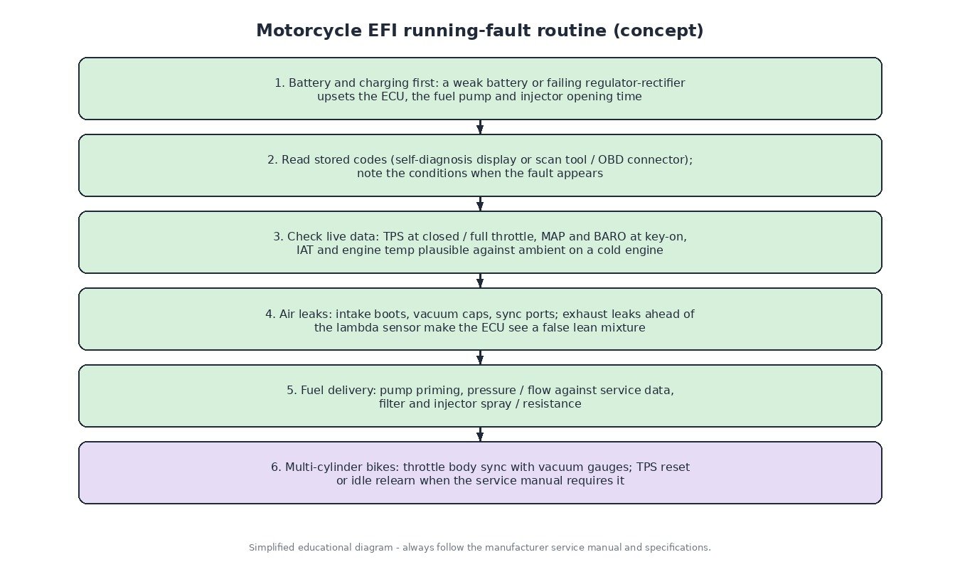
- Power first. A weak battery or failing regulator-rectifier causes erratic running and false sensor codes. Check charging voltage before anything else.
- Read codes. Older bikes flash codes on the dash or use dealer tools; Euro 5 bikes support standardised OBD, so many generic scan tools can read P-codes.
- Live data. Check the TPS at closed and full throttle, compare MAP and BARO at key-on with the engine off, and compare temperature sensors with ambient on a cold engine.
- Leaks. Cracked intake boots, missing vacuum caps on sync ports and exhaust leaks ahead of the lambda sensor all show up as lean running.
- Sync and resets. Multi-cylinder bikes need balanced throttle bodies, set with vacuum gauges. Some models also require a TPS reset or idle relearn after throttle body work, following the service manual.
What this means for calibration
Because many bikes depend on throttle-based fuel tables, hardware changes such as a full exhaust system, a different air filter or modified intake usually need matching fuel and ignition maps. Reading the original file first (by OBD where the bike supports it, or on the bench) and keeping a backup is essential. Bike ECUs are supported by tools such as KESS3, Autotuner, Flex and bench tools, and tables are edited in a calibration editor such as WinOLS. Changes to emissions-relevant functions on road-registered bikes must stay within local law. The same principles apply to ATVs, UTVs, snowmobiles and small petrol engines in utility and agricultural machines.
Related fault codes (DTCs)
Generic OBD-II/EOBD codes (SAE J2012). Many motorcycles, especially pre-Euro 5 models, also use their own numeric service codes, so confirm with the manufacturer’s service information.
| Code | Meaning | Typical causes |
|---|---|---|
| P0105 | Manifold Absolute Pressure/Barometric Pressure Circuit | MAP sensor connector, wiring or 5 V reference fault, failed sensor |
| P0106 | Manifold Absolute Pressure/Barometric Pressure Range/Performance | Split, blocked or disconnected MAP vacuum hose, intake air leak, wrong throttle body sync, sensor drift |
| P0107 | Manifold Absolute Pressure/Barometric Pressure Circuit Low | Signal shorted to ground, open 5 V reference, sensor fault |
| P0108 | Manifold Absolute Pressure/Barometric Pressure Circuit High | Signal shorted to voltage, open sensor ground, sensor fault |
| P0112 | Intake Air Temperature Sensor 1 Circuit Low | Sensor or signal wire shorted to ground, failed NTC sensor |
| P0113 | Intake Air Temperature Sensor 1 Circuit High | Sensor unplugged, open circuit, corroded connector (common on exposed airbox sensors) |
| P0117 | Engine Coolant Temperature Sensor 1 Circuit Low | Sensor or wiring shorted to ground, failed sensor |
| P0118 | Engine Coolant Temperature Sensor 1 Circuit High | Open circuit, unplugged or corroded connector, failed sensor |
| P0120 | Throttle/Pedal Position Sensor/Switch “A” Circuit | TPS wiring or connector fault, worn sensor track, reference voltage problem |
| P0121 | Throttle/Pedal Position Sensor/Switch “A” Circuit Range/Performance | TPS signal implausible against MAP/rpm, worn sensor, TPS not reset after throttle body work, sticking throttle |
| P0122 | Throttle/Pedal Position Sensor/Switch “A” Circuit Low | Signal shorted to ground, open 5 V reference, sensor fault |
| P0123 | Throttle/Pedal Position Sensor/Switch “A” Circuit High | Signal shorted to voltage, open sensor ground, sensor fault |
| P0130 | O2 Sensor Circuit (Bank 1 Sensor 1) | Lambda sensor wiring or connector damage (heat, chain/road debris), failed sensor |
| P0135 | O2 Sensor Heater Circuit (Bank 1 Sensor 1) | Open heater element, blown fuse, heater wiring fault |
| P0171 | System Too Lean (Bank 1) | Intake boot or vacuum leak, exhaust leak ahead of the O2 sensor, low fuel pressure, restricted injector, aftermarket parts without re-calibration |
| P0172 | System Too Rich (Bank 1) | Leaking injector, high fuel pressure, blocked air filter, faulty ECT/IAT reading |
| P0201 | Injector Circuit/Open – Cylinder 1 | Injector coil open, connector or wiring fault, ECU driver fault |
| P0202 | Injector Circuit/Open – Cylinder 2 | Injector coil open, connector or wiring fault, ECU driver fault |
| P0230 | Fuel Pump Primary Circuit | Fuel pump relay, fuse, wiring or connector fault, tip-over / kill-switch circuit in the pump supply |
| P0300 | Random/Multiple Cylinder Misfire Detected | Lean running, ignition faults, low fuel pressure, intake leaks, mechanical problems |
| P0335 | Crankshaft Position Sensor “A” Circuit | Sensor or wiring fault, damaged reluctor/pick-up, connector corrosion |
| P0505 | Idle Air Control System | Sticking or failed ISC valve / stepper, carbon in the bypass passage, wiring fault |
| P0506 | Idle Air Control System RPM Lower Than Expected | Carbon build-up in throttle body or bypass, ISC valve restricted, throttle bodies out of sync |
| P0507 | Idle Air Control System RPM Higher Than Expected | Intake air leak, throttle not fully closing, incorrect idle air screw setting, ISC valve stuck open |
| P0562 | System Voltage Low | Weak battery, failing regulator-rectifier or stator, poor ground or battery terminal connections |
Summary
Motorcycle EFI comes down to one question: how much air is in the cylinder? Know whether the bike answers it with throttle angle, manifold pressure or both, check power, leaks and sync first, and most running faults become much easier to solve.
Fitted a new exhaust or intake and need a custom-made map built from your original read? Send your file to the ECUFileMarket file service.