
When a turbocharger or supercharger compresses intake air, that air leaves the compressor hotter and less dense than ambient. An intercooler — also called a charge-air cooler (CAC) — sits in the charge path to remove some of that heat before the air reaches the cylinders. Cooler charge air carries more oxygen in the same volume, which helps power, combustion control and component protection. This article explains air-to-air versus air-to-water designs, cooler placement, how the ECU uses post-intercooler intake air temperature (IAT), and what fails in the charge pipes and core.
Why compressed air needs cooling
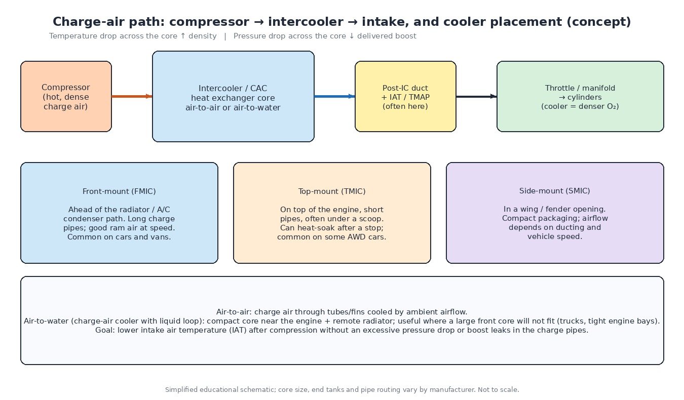
Compression work raises temperature. Hotter air expands, so at a given boost pressure the mass of oxygen in the manifold drops. That matters for petrol engines (knock margin and spark timing) and for diesels (smoke, quantity limits and exhaust temperature). The intercooler is a heat exchanger: charge air passes through tubes or passages while a second fluid — ambient air or a liquid coolant loop — carries heat away. The useful result is a temperature drop across the core and a rise in charge density, ideally without an excessive pressure drop that throws away the boost the compressor just made.
Air-to-air and air-to-water
- Air-to-air: charge air flows through a finned core cooled by ram air and the cooling fan. Simple, robust and common on cars, vans and many trucks.
- Air-to-water: a compact charge-air cooler near the engine transfers heat into a liquid loop that rejects it at a remote radiator. Useful when packaging will not allow a large front core, or when a short charge path is preferred.
Both types must balance cooling against flow restriction. A core that is too small or clogged with oil, soot or debris still drops temperature poorly and can raise the pressure loss the turbo must overcome.
Front-mount, top-mount and side-mount
Front-mount coolers sit ahead of or in the bumper/radiator stack and usually see the best airflow at speed, at the cost of longer charge pipes. Top-mount coolers sit above the engine with short pipes, often under a scoop; they can heat-soak after a hot stop when under-bonnet air rises. Side-mount coolers live in a wing or fender opening; their effectiveness depends on ducting and vehicle speed. Placement changes pipe length, leak risk and how quickly post-cooler IAT recovers after idling in traffic.
Temperature drop, density and pressure drop
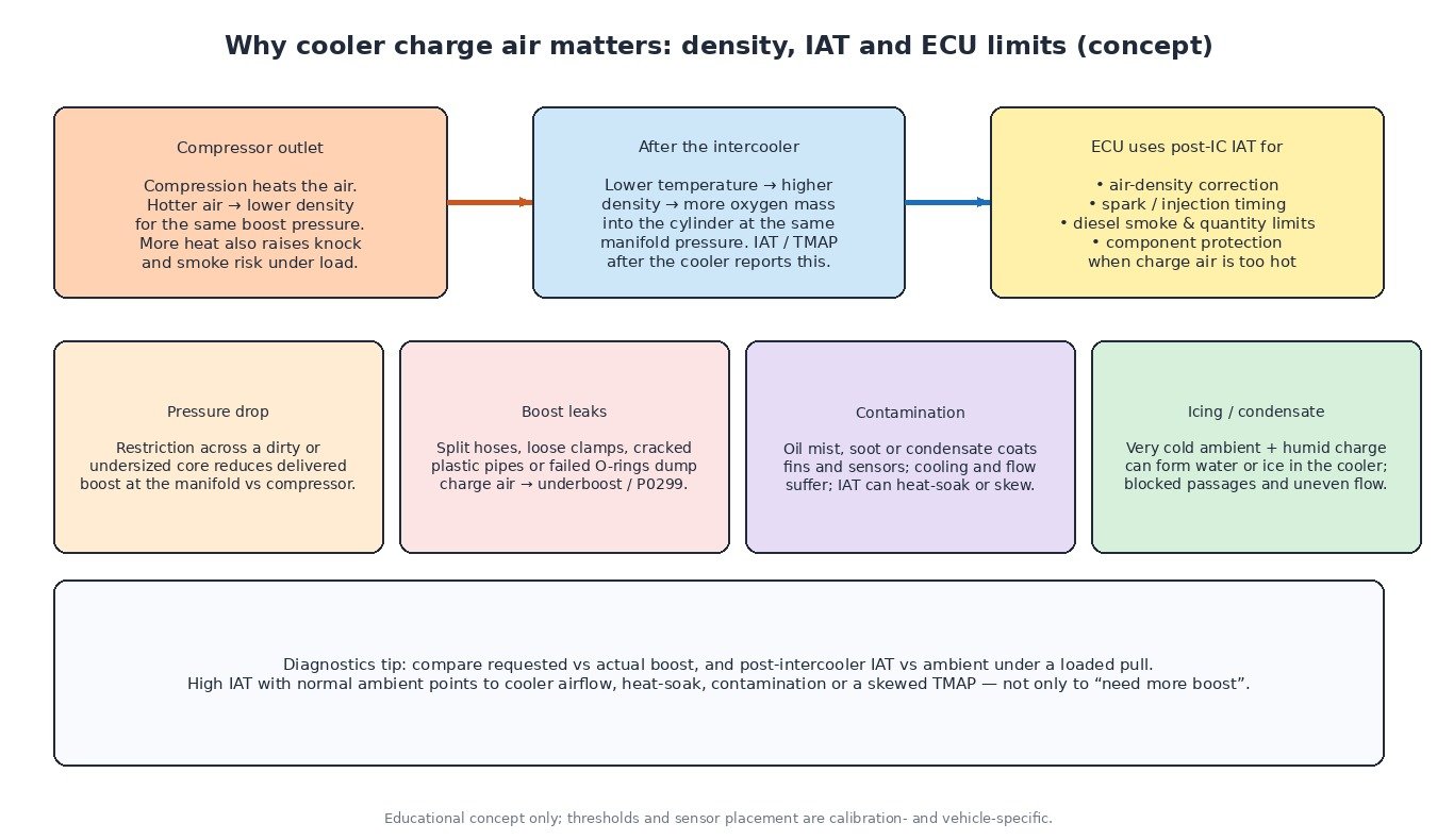
Effectiveness is often discussed as how much the charge temperature falls between compressor outlet and cooler outlet under load. A healthy cooler, clean fins and good airflow produce a clear drop; a heat-soaked or blocked cooler leaves post-IC IAT close to compressor outlet temperature. Density rises when temperature falls at roughly constant pressure — that is the oxygen the ECU is trying to meter. The other side of the ledger is pressure drop across the core and end tanks: too much restriction means manifold pressure lags compressor pressure, which looks like lost boost even when the turbo is healthy.
Where the IAT sensor sits — and why the ECU cares
Many boosted engines place an IAT element, or a combined temperature and pressure sensor (TMAP), in the duct after the intercooler. That reading is closer to what the cylinders see than a pre-compressor or airbox sensor. The ECU uses post-IC IAT for:
- Air-density correction with MAP or MAF so fuel mass matches oxygen mass.
- Spark timing and injection timing adjustments when the charge is hot or cold.
- Diesel smoke and quantity limits that tighten when charge air is hot.
- Component protection — retard, enrichment or torque limit — when post-cooler temperature stays too high under load.
A false cold reading can overfuel; a false hot reading can cut power. Before blaming calibration, compare live IAT with ambient after a cold soak, then watch post-IC IAT on a loaded pull.
Icing, condensation, oil and soot
In cold, humid weather, condensate can form inside the cooler; in extreme cases ice restricts passages. Oil mist from a crankcase ventilation path or leaking turbo seals coats fins and the IAT element. On diesels, soot-laden blow-by or EGR-related deposits can dirty the intake path. Contaminated cores cool less, flow less and make sensors heat-soak or skew — symptoms that look like “needs more boost” when the hardware needs cleaning or repair.
Boost leaks in charge pipes
Split silicone hoses, loose clamps, cracked plastic pipes and failed cooler end-tank welds dump compressed air before the manifold. The ECU sees underboost (often P0299), the turbo may spin harder to compensate, and post-IC pressure may disagree with expected values. A smoke test of the charge system, and logging requested versus actual boost, separate leaks from actuator or sensor faults.
Cars, vans, trucks, ag machines and turbo bikes
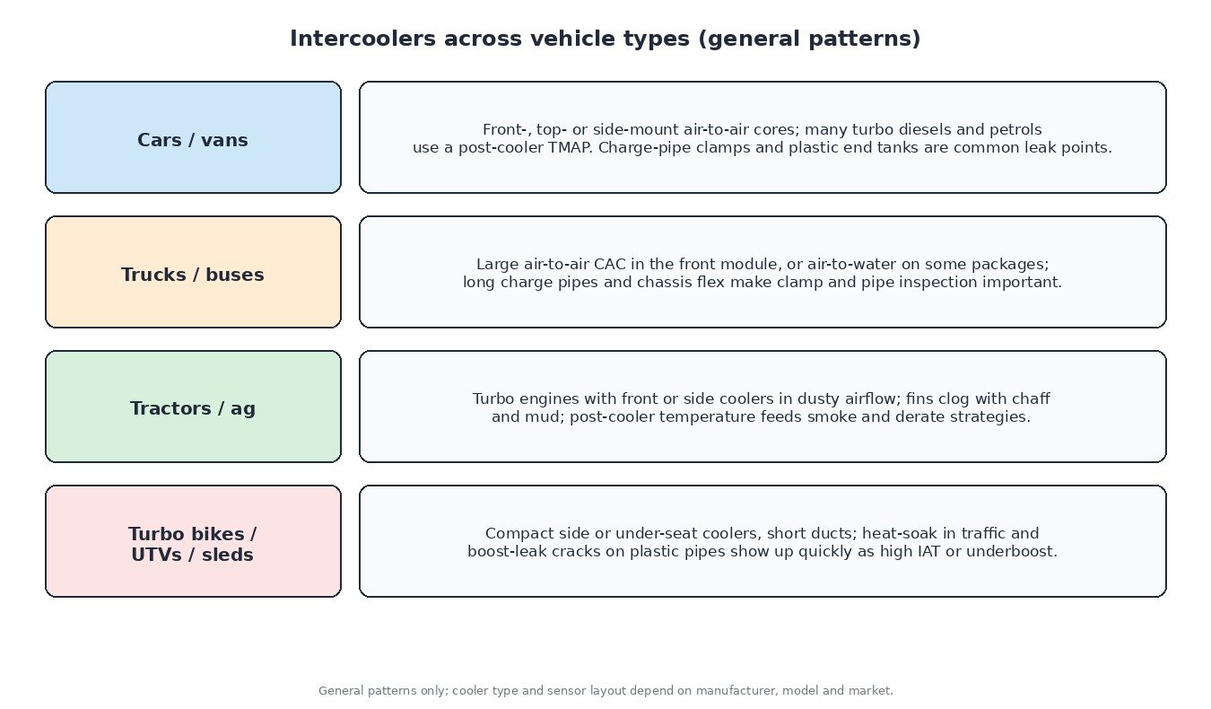
Passenger cars and vans use front-, top- or side-mount air-to-air cores with charge-pipe clamps that loosen with heat cycles. Heavy trucks often run large front CACs or air-to-water packages with long pipes that need clamp and hose inspection. Agricultural engines work in dusty airflow; chaff and mud clog fins and raise IAT under load. Turbo motorcycles, UTVs and snowmobiles use compact coolers and short ducts — heat-soak and cracked plastic pipes show up quickly as high IAT or underboost.
What this means for engineered files
Raising boost without confirming cooler airflow, charge-pipe integrity and honest post-IC IAT is how knock, smoke and over-temperature protections get triggered in the field. Leave IAT scaling alone unless hardware was changed; keep hot-charge protection in place. On ECUFileMarket, engineered ECU and TCU files are delivered through the site upload flow. Checksum correction, when needed, is a separate paid option — it is not included in file prices.
Related fault codes (DTCs)
Generic OBD-II codes (SAE J2012) that often appear with intercooler, charge-pipe and post-IC IAT problems. Manufacturer wording varies.
| Code | Meaning | Typical causes |
|---|---|---|
| P0110 | Intake Air Temperature Sensor 1 Circuit | Open/short in IAT or TMAP temperature circuit, failed sensor, damaged connector after the intercooler |
| P0111 | Intake Air Temperature Sensor 1 Circuit Range/Performance | Implausible IAT vs ambient/ECT, intermittent signal, heat-soaked or contaminated post-IC sensor |
| P0112 | Intake Air Temperature Sensor 1 Circuit Low | Signal shorted to ground or failed sensor (often reads very hot) |
| P0113 | Intake Air Temperature Sensor 1 Circuit High | Open circuit, poor connector or failed sensor (often reads very cold) |
| P0114 | Intake Air Temperature Sensor 1 Circuit Intermittent | Loose pin, chafed harness near charge pipes, heat-related intermittent open/short |
| P0127 | Intake Air Temperature Too High | Genuine hot charge air, clogged/heat-soaked intercooler, blocked airflow, skewed high IAT reading |
| P0070 | Ambient Air Temperature Sensor Circuit | Fault in ambient (outside air) temperature circuit where used for plausibility or derate |
| P0071 | Ambient Air Temperature Sensor Range/Performance | Implausible ambient vs IAT after soak; damaged ambient sensor or wiring |
| P0072 | Ambient Air Temperature Sensor Circuit Low | Ambient sensor or wiring shorted low |
| P0073 | Ambient Air Temperature Sensor Circuit High | Ambient sensor open or shorted high |
| P0234 | Turbocharger/Supercharger “A” Overboost Condition | Wastegate/VGT stuck closed, boost control fault; less often a sensor error — confirm with live data |
| P0299 | Turbocharger/Supercharger “A” Underboost Condition | Charge-pipe/hose leak, loose clamp, cracked cooler end tank, wastegate stuck open, restricted CAC |
| P0236 | Turbocharger/Supercharger Boost Sensor “A” Circuit Range/Performance | Implausible boost/TMAP reading vs expected; leak, hose off sensor, or failing pressure element |
| P0237 | Turbocharger/Supercharger Boost Sensor “A” Circuit Low | Boost/MAP signal low: open/short, unplugged TMAP, large leak downstream of compressor |
| P0238 | Turbocharger/Supercharger Boost Sensor “A” Circuit High | Boost/MAP signal high: short to voltage, failed sensor, or wiring fault on shared TMAP connector |
| P0069 | Manifold Absolute Pressure – Barometric Pressure Correlation | MAP/baro disagree at key-on or idle; sensor fault, vacuum/boost hose issue, or baro reference problem |
| P2226 | Barometric Pressure Sensor “A” Circuit | Baro sensor circuit fault (internal or external); affects altitude and boost correlation checks |
| P2227 | Barometric Pressure Sensor “A” Circuit Range/Performance | Implausible baro vs MAP at key-on; contaminated or failing baro element |
| P2228 | Barometric Pressure Sensor “A” Circuit Low | Baro signal low: wiring short/open or failed sensor |
| P2229 | Barometric Pressure Sensor “A” Circuit High | Baro signal high: wiring short to voltage or failed sensor |
Closing
An intercooler turns hot compressed air into a denser, cooler charge. Keep the core clean, the pipes sealed and the post-IC IAT reading honest — then the ECU can meter fuel and protect the engine correctly.
Need an engineered ECU or TCU file for a car, van, truck, tractor or bike? Upload your original read at ECUFileMarket.