
Open the intake manifold of a modern diesel or petrol direct-injection engine and you will often find small butterflies sitting just ahead of the inlet ports. These intake manifold flaps, called swirl flaps, tumble flaps or intake runner valves depending on design, are moved by the engine control unit to change how air enters the cylinder. They are small parts with a large influence on combustion, emissions and low-speed drivability. This guide explains how they work, how the ECU controls them and what technicians should know when they fail.
Why the air needs to move
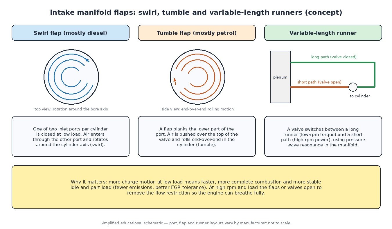
Combustion is faster and more complete when the charge inside the cylinder is moving in an organised way. At high engine speed the intake air is already flowing fast and creates plenty of motion by itself. At idle and part load the air speed is low, so mixing of fuel and air is slower. Engineers solve this by deliberately shaping the airflow at low load, then removing the restriction when the engine needs maximum breathing.
Two types of organised charge motion are used:
- Swirl: the air rotates around the axis of the cylinder bore, like water circling a drain. It is especially useful in diesels, where fuel is injected into the air and needs to meet oxygen quickly.
- Tumble: the air rolls end-over-end, along the axis of the cylinder. Many petrol direct-injection engines use tumble to help mix the fuel spray and to keep combustion stable during catalyst heating or with high EGR rates.
Three designs you will find
Swirl flaps
Diesels with four valves per cylinder often have two inlet ports per cylinder. A swirl flap closes one of them at low load. All of the air then enters through the remaining port, offset from the centre, which sets up strong swirl. As rpm and load increase, the flap opens and both ports flow freely.
Tumble flaps
In a tumble system, a flap partly blanks the lower section of the inlet port. The air is pushed over the top of the valve head and drops into the cylinder along the far wall, starting a rolling motion. When the flap opens, the full port cross-section is available again.
Variable-length runners
A variable intake manifold uses a valve to switch between a long and a short air path. Pressure waves in the intake runners can be used to push extra air into the cylinder, and the best runner length depends on engine speed. A long path helps low and mid-range torque, a short path helps at high rpm. Some V engines use a tuning valve that connects two plenums instead of changing runner length directly. The principle is the same: use resonance to fill the cylinders better across the rev range.
How the ECU controls the flaps
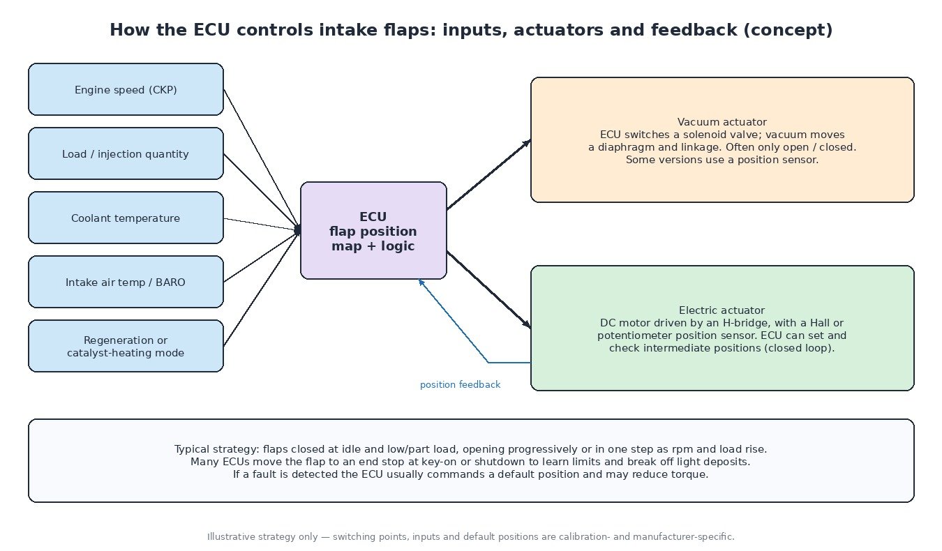
Flap position is a calibrated output like any other. The ECU reads engine speed, load or injected quantity, coolant and intake air temperature and barometric pressure, then selects a target position from its maps. Special operating modes, such as DPF regeneration on diesels or catalyst heating on petrol engines, can use their own flap strategy.
Vacuum actuators
Older and simpler systems use a vacuum diaphragm actuator. The ECU switches a solenoid valve that applies vacuum from the vacuum pump or intake to the diaphragm, which moves a linkage. These systems are often simply open or closed, and only some have a position sensor to confirm movement.
Electric actuators
Most current systems use a small DC motor driven by the ECU through an H-bridge output, with a Hall-effect or potentiometer position sensor. The ECU can command intermediate positions and compare commanded with actual position continuously. Many systems drive the flap to an end stop at key-on or shutdown to learn the limits, which also helps to break off light deposits.
Common problems
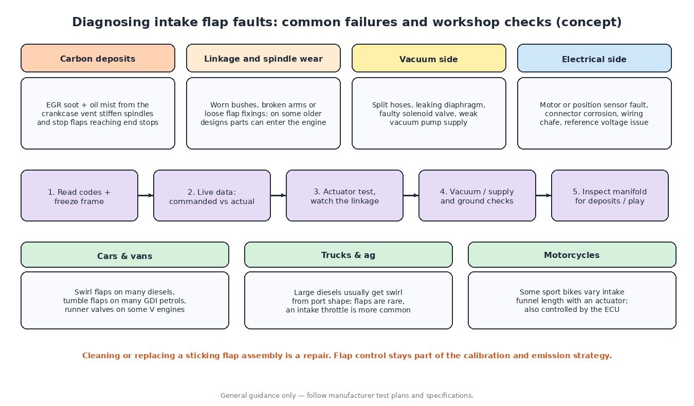
- Carbon build-up. Exhaust gas recirculation brings soot into the intake, and the crankcase ventilation adds oil mist. Together they form sticky deposits that stiffen flap spindles and stop flaps reaching their end positions.
- Mechanical wear. Spindle bushes, plastic levers and linkages wear over time. On some older designs, worn flap spindles or fixings have come loose and entered the cylinder, causing serious engine damage. That is one reason why inspecting the manifold matters on high-mileage engines.
- Vacuum faults. Split hoses, a leaking diaphragm or a faulty solenoid valve leave a vacuum-operated flap in the wrong position.
- Electrical faults. Motor failure, position sensor faults, corroded connectors and chafed wiring set circuit codes.
Symptoms include rough idle, a flat spot at low rpm, more smoke on diesels, poor response and, in many cases, a warning lamp with a reduced torque mode.
Cars, trucks, agricultural machines and motorcycles
Passenger cars and vans are where flaps are most common: swirl flaps on many diesels, tumble flaps on many petrol direct-injection engines and runner valves on some larger petrol engines. Heavy trucks and agricultural tractors usually generate swirl through the shape of the inlet ports themselves, so separate flaps are rare and an electronic intake throttle is the more typical intake actuator. Motorcycles occasionally use variable-length intake funnels on high-performance engines, moved by an actuator under ECU control, applying the same resonance principle as a car’s variable manifold.
What it means for ECU calibration
Flap maps interact with fuelling, injection timing, EGR, boost and emissions. A file that changes torque or air demand has to respect the flap strategy, its switching points and its diagnostics. A sticking or broken flap is a mechanical repair, not something to hide in software, and flap control stays part of the engine’s emission strategy. Before any software work, confirm the flaps move freely and follow the command in live data, because a stuck flap will distort any datalog you take.
Related fault codes (DTCs)
Generic OBD-II codes (SAE J2012). Manufacturers may use their own codes and wording for flap faults, and bank numbering depends on the engine.
| Code | Meaning | Typical causes |
|---|---|---|
| P2004 | Intake Manifold Runner Control Stuck Open (Bank 1) | Flap seized open by carbon, broken linkage, no vacuum to the actuator, actuator failure |
| P2005 | Intake Manifold Runner Control Stuck Open (Bank 2) | Same causes as P2004, on the bank 2 flaps |
| P2006 | Intake Manifold Runner Control Stuck Closed (Bank 1) | Flap seized closed, sticking spindle, actuator stuck, vacuum held by a faulty solenoid valve |
| P2007 | Intake Manifold Runner Control Stuck Closed (Bank 2) | Same causes as P2006, on the bank 2 flaps |
| P2008 | Intake Manifold Runner Control Circuit/Open (Bank 1) | Open circuit in the actuator or solenoid wiring, unplugged connector, failed coil or motor |
| P2009 | Intake Manifold Runner Control Circuit Low (Bank 1) | Short to ground in the control circuit, damaged actuator |
| P2010 | Intake Manifold Runner Control Circuit High (Bank 1) | Short to voltage, internal actuator fault |
| P2014 | Intake Manifold Runner Position Sensor/Switch Circuit (Bank 1) | Position sensor or wiring fault, missing reference voltage or ground |
| P2015 | Intake Manifold Runner Position Sensor/Switch Circuit Range/Performance (Bank 1) | Flap not reaching the commanded position, worn linkage, carbon deposits, sensor out of range |
| P2016 | Intake Manifold Runner Position Sensor/Switch Circuit Low (Bank 1) | Short to ground, open reference supply, failed sensor |
| P2017 | Intake Manifold Runner Position Sensor/Switch Circuit High (Bank 1) | Open signal or ground circuit, short to voltage, failed sensor |
| P0660 | Intake Manifold Tuning Valve Control Circuit/Open (Bank 1) | Tuning (runner length) valve actuator or wiring open circuit |
| P0661 | Intake Manifold Tuning Valve Control Circuit Low (Bank 1) | Short to ground in the tuning valve circuit |
| P0662 | Intake Manifold Tuning Valve Control Circuit High (Bank 1) | Short to voltage, failed tuning valve actuator |
| P0300 | Random/Multiple Cylinder Misfire Detected | Many causes; check for loose flap parts or a damaged inlet valve if flaps have failed mechanically |
Closing
Intake flaps turn a fixed intake into one that adapts to load and rpm. Knowing which type an engine uses, how the ECU commands it and how to confirm movement makes flap faults quick to diagnose.
Need a custom engineered ECU or TCU file built from your original read? Upload your file at ECUFileMarket.