
Pull a tractor into a heavy cultivator pass, engage a 1000 rpm PTO on a forage harvester, or switch on a big load on a generator, and the engine has to react in a fraction of a second to keep its speed. The part of the engine control unit (ECU) that does this is the governor. On modern diesels it is pure software, and this guide explains how it works and how to diagnose hunting, surging and poor PTO speed control.
What a diesel governor does
A petrol engine’s power is controlled mainly by the amount of air it can draw in. A diesel has no throttle in the traditional sense: it breathes freely and its power is set by how much fuel is injected. Without control, an unloaded diesel would over-rev and a loaded one would stall. The governor’s job is to meter fuel so the engine holds the speed the operator asks for, does not drop below idle, and never exceeds its safe maximum speed.
Mechanical vs electronic governors
Older in-line and rotary injection pumps used a mechanical governor: flyweights spun by the pump shaft pushed against springs, and the balance between centrifugal force and spring force moved the fuel control rack. Speed lever position changed the spring preload and therefore the governed speed.
An electronic governor replaces the flyweights with a crankshaft speed signal and software. The ECU calculates the fuel quantity needed and commands it through a rack actuator, a metering valve or, on common rail and unit injector systems, the injector energising time. Being software, its response can vary with temperature, mode, gear and CAN messages.
All-speed vs min-max governing
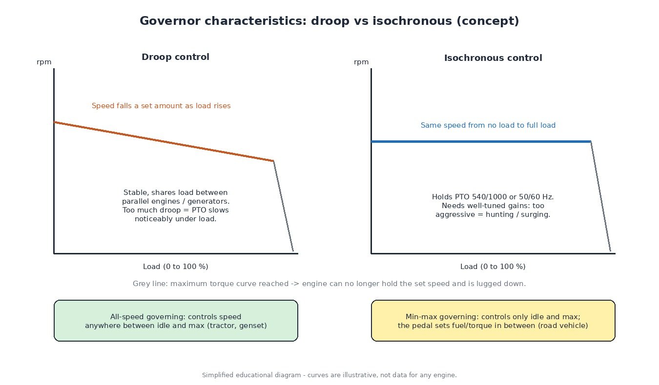
- All-speed (variable-speed) governing – the hand throttle or pedal sets a target speed anywhere between idle and maximum, and the ECU adds or removes fuel to hold it. Normal for tractors, combines, construction machines and gensets.
- Min-max governing – only idle speed and maximum speed are governed. In between, the pedal effectively requests fuel or torque, and the driver controls speed. This suits cars and many trucks.
Many modern trucks and tractors offer both: min-max for road work and all-speed (sometimes called PTO or work mode) for stationary or field work.
Droop vs isochronous control
Droop means governed speed falls slightly as load increases. It is very stable and lets paralleled generators share load. Isochronous control holds the same speed from no load to full load, which is what a PTO-driven implement or a single generator supplying a fixed frequency needs. Electronic governors can usually switch between the two, and the amount of droop is a calibration value set by the manufacturer. Once the engine reaches its maximum torque curve, no governor can hold speed any more and the engine is lugged down.
PTO 540/1000, engine speed memory and hand throttle
Implements are designed around standard PTO shaft speeds of 540 or 1000 rpm (and economy variants on many tractors). The engine speed needed to reach them depends on the PTO gearing. To make this repeatable, tractors offer engine speed memory: the operator stores one or two speeds and recalls them with a button, often at the headland. The ECU then governs isochronously at that speed while the hand throttle or memory is active, and returns to pedal control when it is cancelled.
How the ECU closes the loop
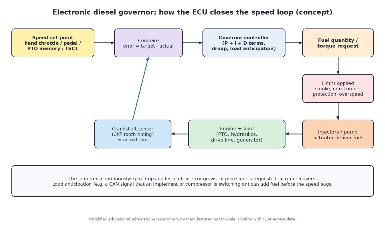
Actual speed comes from the crankshaft position (CKP) sensor: the ECU measures the time between tone wheel teeth and converts it to rpm, often many times per revolution. It compares that with the target and the difference (the speed error) feeds a controller that works like a PID loop:
- the proportional part reacts to how big the error is now;
- the integral part removes the remaining steady error over time, which is what makes isochronous control possible;
- the derivative part, or similar damping, reacts to how quickly speed is changing.
The output is a fuel quantity or torque request, which then passes through limits such as smoke limitation, maximum torque and component protection before reaching the injectors. Load anticipation improves response further: if the ECU knows a load is about to arrive, for example an air conditioning compressor or a hydraulic function signalled over CAN, it can add fuel before rpm sags. Our crankshaft and camshaft sensor guide explains the speed signal in more detail.
J1939 TSC1 requests from implements and the TCU
On trucks and agricultural machines the engine does not only obey the pedal. Other controllers can send a Torque/Speed Control 1 (TSC1) message over the SAE J1939 CAN bus, asking the engine for a specific speed or a torque limit. Transmissions use it during shifts, retarders and ABS to cut torque, and on tractors an implement can request engine speed through ISOBUS tractor-implement management. The ECU arbitrates between the operator and these requests according to priority rules in its software.
Overspeed protection
Every governor includes a maximum speed limit, and above it the ECU cuts fuel. A diesel can still overspeed if it is driven by the vehicle on a steep descent in too low a gear, or if it is fed from an uncontrolled source such as engine oil. That is why overspeed events are logged (P0219 or J1939 SPN 190 with FMI 0) and should always be investigated. Our ECU limiters guide covers rev and road speed limiters.
Common symptoms
- Hunting or surging – rpm rises and falls rhythmically. Look at air in the fuel, filters and lift pump, the CKP signal, the hand throttle sensor and injector balance.
- Too much droop – speed falls noticeably as load comes on. Confirm the mode, then check fuel supply, rail pressure and air intake.
- Won’t hold PTO speed – the memory speed is selected but rpm wanders or drops. Check the switches, active TSC1 requests and codes in other modules.
Diagnostic routine
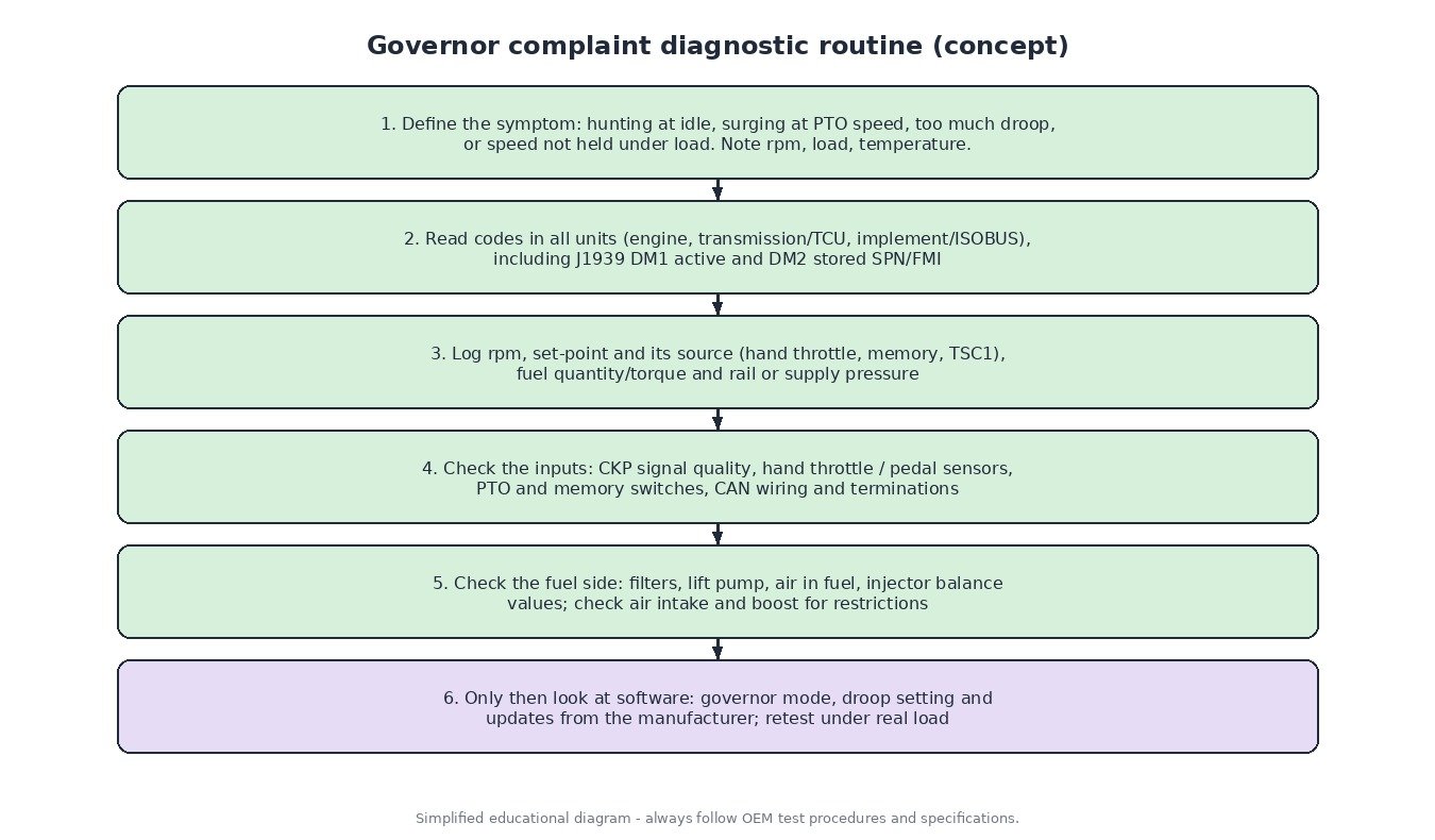
- Reproduce the complaint and note rpm, load, temperature and operating mode.
- Read codes in every module, including J1939 active (DM1) and stored (DM2) codes.
- Log actual speed, target speed and its source, injected quantity or torque, and fuel pressure.
- Check the speed sensor, throttle inputs, switches and CAN wiring.
- Check the fuel system and air intake before blaming the software.
- Check for manufacturer software updates and retest under real load.
Calibration concepts
Governor behaviour is defined by calibration data: target speed tables, droop values, controller gains and their dependence on temperature, gear and mode, plus the limits that apply to the final torque request. Any change must keep the protection limits, smoke limitation and all emissions systems fully intact and working as designed.
Related fault codes (DTCs)
Generic OBD-II/EOBD codes (SAE J2012) and common J1939 SPNs. Wording varies by manufacturer and off-highway machines often use their own code lists, so always confirm with service information.
| Code | Meaning | Typical causes |
|---|---|---|
| P0219 | Engine Overspeed Condition | Engine driven above its permitted speed: downhill overrun or wrong gear selection, sudden loss of load, a mechanical fault feeding extra fuel, or (rarely) an implausible speed signal |
| P0335 | Crankshaft Position Sensor “A” Circuit | Open or shorted sensor wiring, failed sensor, damaged connector, missing or damaged reluctor teeth |
| P0336 | Crankshaft Position Sensor “A” Circuit Range/Performance | Incorrect air gap, debris on the sensor tip, damaged tone wheel, electrical noise from poor screening or a faulty alternator; can cause erratic governed speed |
| P0337 / P0338 | Crankshaft Position Sensor “A” Circuit Low / High | Short to ground or to supply, sensor supply fault on Hall-type sensors, connector corrosion |
| P0339 | Crankshaft Position Sensor “A” Circuit Intermittent | Chafed harness, loose terminals, signal dropouts that appear with vibration or heat; a classic cause of intermittent hunting or stalling |
| P0120 – P0123 | Throttle/Pedal Position Sensor/Switch “A” Circuit / Range/Performance / Low / High | Worn hand throttle or pedal sensor track, 5 V reference or ground fault, water in the connector, damaged wiring |
| P2135 | Throttle/Pedal Position Sensor/Switch “A”/”B” Voltage Correlation | The two redundant tracks of a sensor disagree: worn sensor, poor ground, high-resistance connector; the ECU often limits speed or torque as a precaution |
| P0500 | Vehicle Speed Sensor “A” | Missing or implausible road/ground speed signal, which can affect road speed governing, cruise and some transmission strategies |
| P0571 | Brake Switch “A” Circuit | Misadjusted or failed brake switch, wiring fault; can cancel cruise or speed-hold functions on vehicles that use it |
| P0216 | Injector/Injection Timing Control Circuit | Timing actuator or solenoid fault on electronically controlled injection pumps, wiring problems, internal pump wear |
| P0251 | Injection Pump Fuel Metering Control “A” (Cam/Rotor/Injector) | Fuel quantity actuator or metering solenoid fault on electronically governed pumps, wiring, internal pump fault; often shows up as poor speed control |
| U0100 / U0101 | Lost Communication With ECM/PCM “A” / With TCM | CAN wiring or termination fault, module power or ground loss; external speed or torque requests stop arriving |
| SPN 190 | J1939 Engine Speed | With FMI 0 (above normal range, most severe) often reported as an overspeed event; FMI 2 points to an erratic or intermittent speed signal |
| SPN 91 | J1939 Accelerator Pedal Position 1 | With FMI 3 / FMI 4 (voltage above / below normal): sensor, reference or ground wiring faults on the pedal or hand throttle input |
Closing
A governor is just a fast speed loop: a clean speed signal, correct set-point, healthy fuel supply and sensible calibration. Check them in that order and most hunting, droop and PTO speed complaints are solved without guesswork.
Need a custom engineered ECU or TCU file for a tractor, truck or car built from your original read? Upload your file at ECUFileMarket.