
Every running engine leaks a little combustion gas past its piston rings into the crankcase. That gas, called blow-by, carries unburned fuel, water vapour, soot and a fine mist of oil. If it stayed trapped, crankcase pressure would push oil out of every seal, and the oil itself would turn to sludge. The crankcase ventilation system (PCV on petrol engines, often called CCV on diesels) removes those gases, separates the oil out of them and sends them back into the intake to be burned. This guide explains how the system works, how it affects the ECU and fuel trims, how it fails, and how to diagnose it on cars, vans, trucks, tractors and motorcycles.
What blow-by is and why it must be managed
Piston rings never seal perfectly. During the combustion stroke a small amount of high-pressure gas slips past the rings into the crankcase. On a healthy engine the volume is modest; on a worn engine, or one under very high cylinder pressure, it rises sharply. Blow-by gas contains hydrocarbons and acids that degrade the oil, and water that condenses when the engine is cold.
Early engines simply vented the crankcase to the atmosphere. Emission rules ended that for road vehicles, and closed systems that route the gas back into the intake became standard.
How a closed crankcase ventilation system works
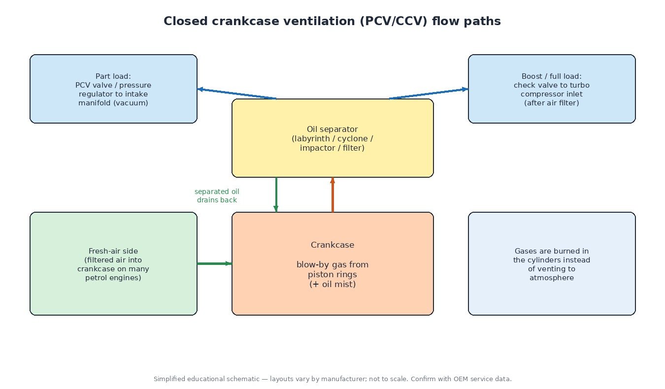
The basic idea is simple: use the pressure difference between the crankcase and the intake to pull the gases out in a controlled way. The main parts are:
- Oil separator – a labyrinth, cyclone, impactor plate or fibre filter element that makes the oil droplets collide with surfaces and drain back to the sump. Some modern engines use an active, electrically driven separator for better efficiency.
- PCV valve or pressure regulator – a spring-loaded valve or diaphragm that limits how much vacuum is applied to the crankcase. At idle, when manifold vacuum is high, it restricts flow; at higher load it opens more. Many modern engines build this regulator into the valve cover or separator module.
- Two paths on turbocharged engines – at part load the gases go to the intake manifold, which is under vacuum. Under boost the manifold is pressurised, so check valves close that path and the gases are drawn instead into the turbo compressor inlet, after the air filter.
- Fresh-air (breather) side – many petrol engines feed a small amount of filtered air into the crankcase to sweep out moisture and fuel vapour.
- Heaters – in cold climates some systems use heated hoses or connectors so that water in the gas does not freeze and block the path.
How the system affects the ECU
The ECU usually does not control the PCV valve directly, but it feels the system in several ways. On engines with a mass airflow (MAF) sensor, crankcase gas enters downstream of the sensor, so the ECU must account for it. A split hose or a torn regulator diaphragm adds unmetered air, and the oxygen sensor feedback shows it as positive (lean) fuel trims, mainly at idle where the leak is a large share of total airflow. On speed-density engines the extra air raises manifold pressure and idle speed.
On diesels, oil carried over from a poor separator coats the intake, the intercooler and the EGR mixing area, and adds to carbon build-up. Many newer vehicles also monitor the system, for example with a detection wire or switch in the hose connector that flags a disconnected line.
Common failures and symptoms
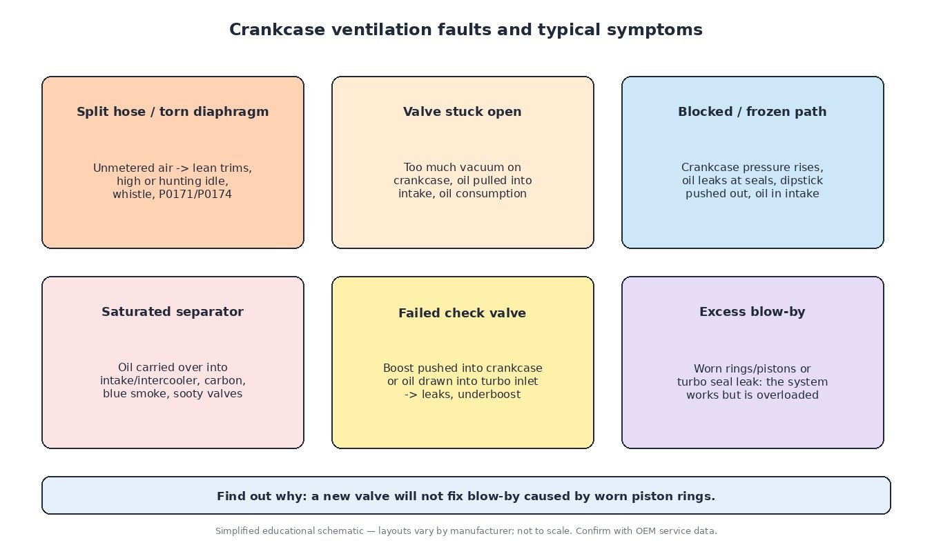
- Split hose or torn diaphragm – lean fuel trims, high or hunting idle, a whistling or hissing noise, sometimes misfires at idle.
- Valve stuck open – too much vacuum on the crankcase, oil drawn into the intake, higher oil consumption and a strong suction at the oil filler opening.
- Blocked or frozen path – crankcase pressure rises, oil leaks at the crankshaft seals and gaskets, the dipstick may be pushed up, and oil can be forced into the air intake.
- Saturated or failed separator – oil in the intake and intercooler, carbon on valves, blue smoke.
- Failed check valve on turbo engines – boost pushed into the crankcase, or oil drawn into the turbo inlet, with oil leaks and sometimes underboost.
- Excessive blow-by – worn rings or pistons, or a turbo seal leak, can overload a healthy system. The ventilation parts then look guilty but are not the cause.
A logical diagnostic order
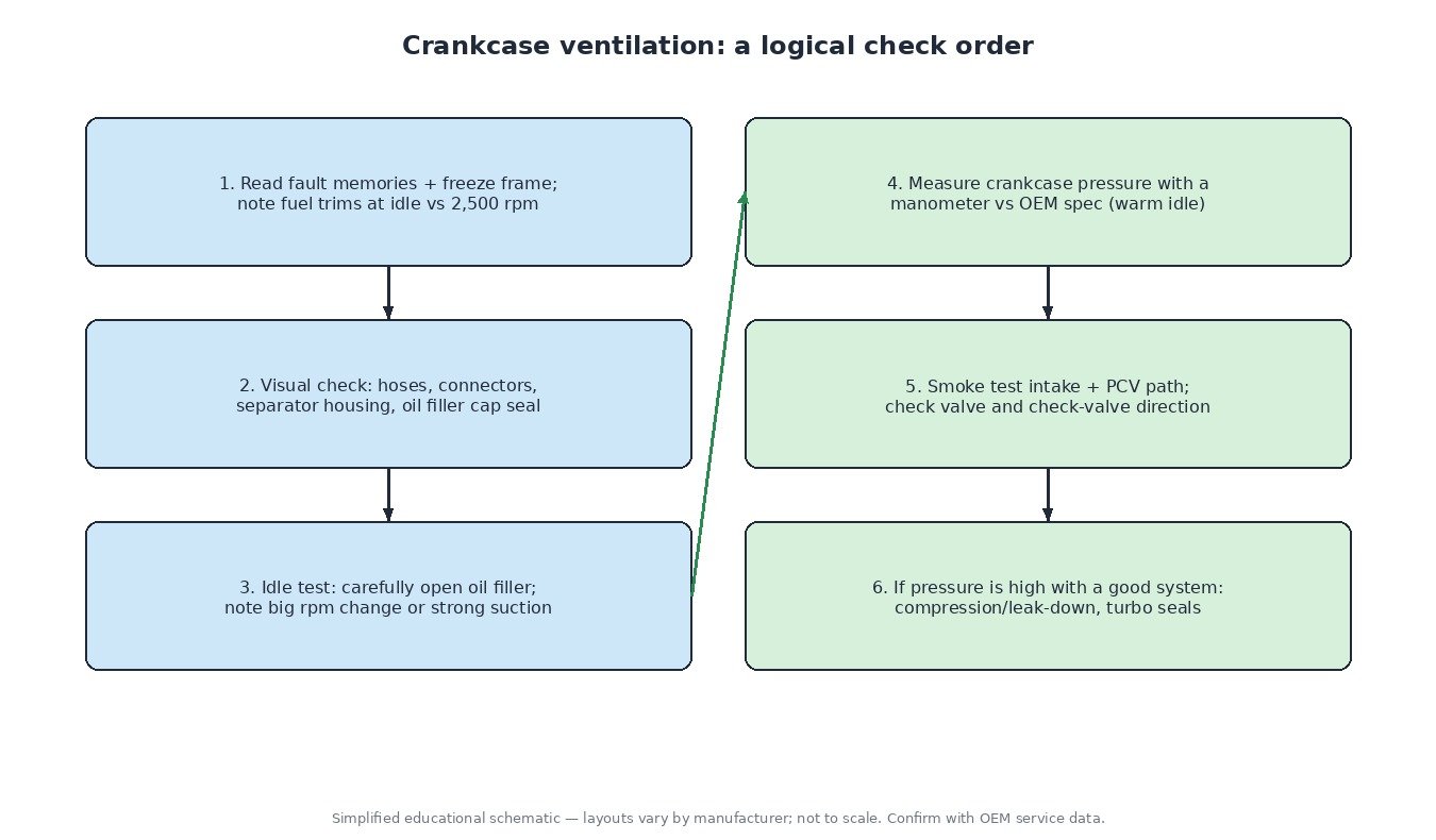
- Read all fault memories and freeze frame. Note the fuel trims at idle and at around 2,500 rpm: a lean condition that improves with rpm points to a vacuum leak, including the PCV path.
- Visual check of all ventilation hoses, quick connectors, the separator housing and the oil filler cap seal.
- Idle check: carefully loosen the oil filler cap at idle. A large change in idle speed, a strong suction or heavy pulsing gas flow is worth investigating, but compare with a known good engine of the same type.
- Measure crankcase pressure with a manometer through the dipstick tube or filler, using the manufacturer’s procedure and specification. This is the most objective test.
- Smoke test the intake and the ventilation path to find leaks, and check that each check valve only flows in its intended direction.
- If pressure is still high with a healthy ventilation system, move on to compression and leak-down tests and check the turbo seals and oil drain.
Trucks, tractors and motorcycles
Heavy-duty truck and agricultural diesels produce large volumes of blow-by. Many use a closed crankcase ventilation unit with a replaceable filter element or a centrifugal separator driven by oil pressure or electrically, and the filter has a service interval that is easy to forget. A clogged element raises crankcase pressure and pushes oil out of seals and the turbo. Motorcycles usually route crankcase gas through a breather and simple separator into the airbox; a full catch area or blocked breather on a bike can put oil into the air filter and throttle bodies.
What it means for ECU calibration
A calibration cannot fix a mechanical ventilation problem. Before any remap, fuel trims should be close to normal, there should be no vacuum leaks, and crankcase pressure should be within specification, because more power and boost also mean more blow-by. The crankcase ventilation system is part of the emissions equipment and should stay intact and working. Always keep the original ECU read as a backup.
Related fault codes (DTCs)
| Code | Meaning | Typical causes |
|---|---|---|
| P04DB | Crankcase Ventilation System Disconnected | Ventilation hose or connector not fully seated or disconnected, broken detection wire or switch in the connector, damaged hose |
| P052E | Positive Crankcase Ventilation Regulator Valve Performance | Torn regulator diaphragm, PCV valve stuck open or closed, leaking valve cover/separator module |
| P053A | Positive Crankcase Ventilation Heater Control Circuit/Open | Open heater element or wiring, poor connector, blown fuse |
| P053B | Positive Crankcase Ventilation Heater Control Circuit Low | Heater circuit shorted to ground, damaged wiring |
| P053C | Positive Crankcase Ventilation Heater Control Circuit High | Heater circuit shorted to voltage, faulty heater or driver |
| P0171 | System Too Lean (Bank 1) | Vacuum leak including split PCV hose or torn diaphragm, MAF contamination, low fuel pressure, exhaust leak before the oxygen sensor |
| P0174 | System Too Lean (Bank 2) | Same as P0171 on bank 2; a leak common to both banks (such as the PCV path) usually sets both codes |
| P2279 | Intake Air System Leak | Unmetered air after the MAF, including ventilation hoses, oil filler cap, intake gaskets or brake booster hose |
| P0507 | Idle Air Control System RPM Higher Than Expected | Vacuum leak via PCV path or hoses, throttle body issues, idle control fault |
| P0101 | Mass or Volume Air Flow Sensor “A” Circuit Range/Performance | Unmetered air, oil-contaminated or dirty MAF, intake leaks, sensor fault |
| P0300 | Random/Multiple Cylinder Misfire Detected | Large vacuum leak causing lean misfire at idle, ignition or fuel faults, low compression |
Code wording follows SAE J2012 generic definitions. Many manufacturers also use their own codes for crankcase ventilation monitoring, so always check the OEM description for the vehicle.
Summary
Crankcase ventilation keeps oil clean, seals dry and crankcase gases out of the atmosphere. When it fails it shows up as lean trims, idle problems, oil leaks or oil in the intake. Diagnose it with trims, a smoke test and a crankcase pressure measurement, and remember that excessive blow-by from engine wear can make a healthy system look faulty.
Need a professional calibration file for your car, truck, tractor or bike? Upload your original read to the ECUFileMarket file service and get a tested file from our tuning team.