
Every sequential injection and coil-on-plug ignition strategy starts with two small magnetic sensors: the crankshaft position (CKP) sensor and the camshaft position (CMP) sensor. Together they tell the engine control unit how fast the engine is turning, where the crank is in its 360° rotation, and which stroke each cylinder is on in the 720° four-stroke cycle. This guide explains inductive versus Hall-effect designs, missing-tooth reluctor wheels, how the ECU builds sync, and how to diagnose faults before condemning parts.
What CKP and CMP actually measure
The CKP sensor watches a toothed wheel on the crankshaft, flywheel or harmonic balancer. From the tooth pattern it measures rotational speed (rpm) and crank angle. The CMP sensor watches a wheel, disc or target on a camshaft — or, on some diesels, on the injection pump. Its job is phase: which half of the four-stroke cycle the engine is in. Without phase, the ECU may know that a piston is at top dead centre, but not whether that cylinder is on compression or exhaust.
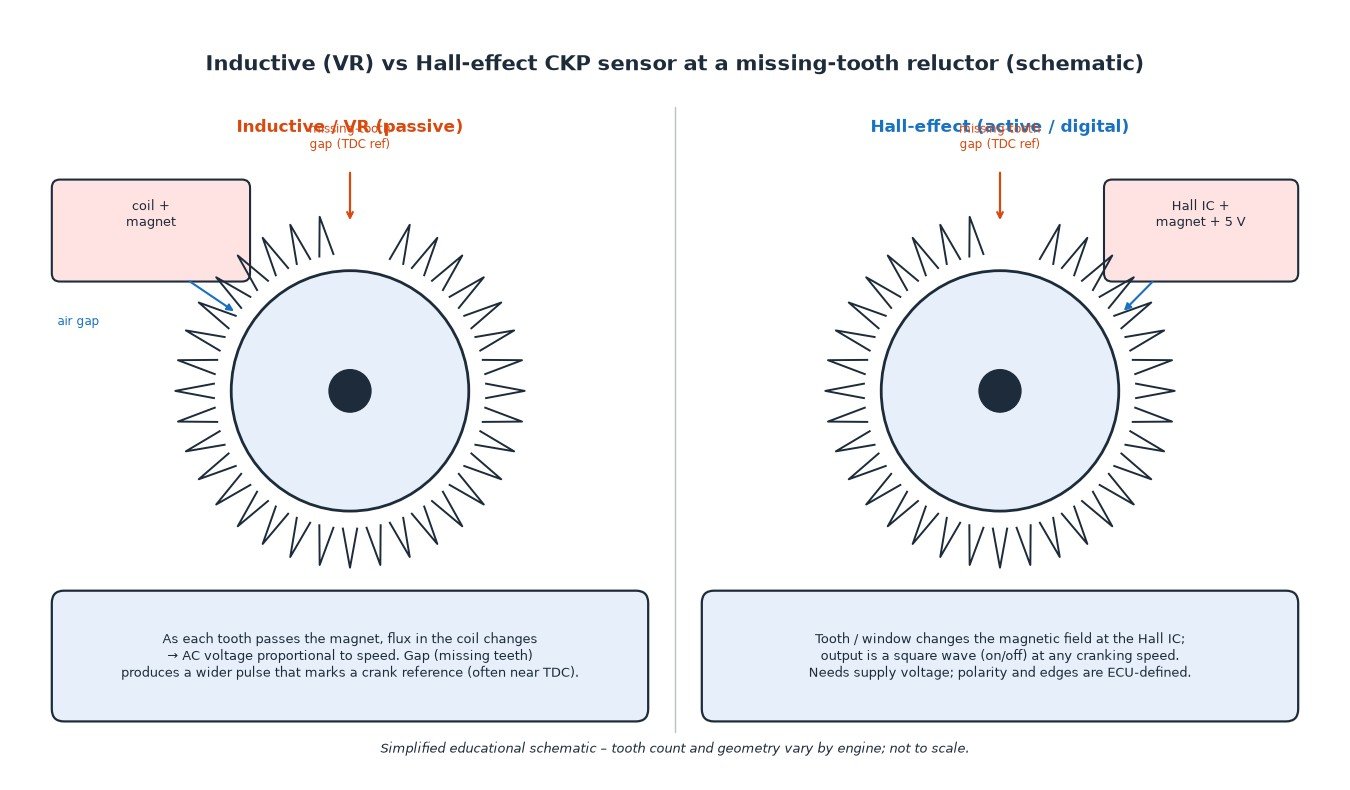
Inductive (VR) versus Hall-effect sensors
Two sensing principles dominate production engines:
- Inductive / variable-reluctance (VR) – a coil and permanent magnet. As each tooth passes, the changing magnetic flux induces an AC voltage. Amplitude rises with speed, so the signal is weak at cranking and strong at high rpm. No supply voltage is needed. The ECU looks at zero-crossings or peaks and expects a characteristic wider pulse at the missing-tooth gap.
- Hall-effect (active / digital) – a Hall IC, magnet and usually a 5 V supply. Teeth or windows switch the magnetic field; the output is a clean square wave even at very low speed. Edge polarity and duty cycle are defined by the ECU and sensor design.
Air gap is critical on both types. Too large and the signal collapses; too small risks mechanical contact or metallic debris bridging the gap.
Missing-tooth and multi-tooth wheels
Most modern crank wheels use a missing-tooth pattern (for example 60-2 or 36-2): a regular tooth pitch with one or two teeth omitted. The longer interval is the absolute crank reference the ECU uses to locate a known angle — often near cylinder 1 TDC. Some older or motorcycle systems use multi-tooth wheels without a gap and rely on a separate CMP pulse, or a dual-track CKP with a second sync mark. Whatever the pattern, the ECU’s tooth decoder must match the hardware; a wrong wheel or damaged tooth count produces range/performance codes and lost sync.
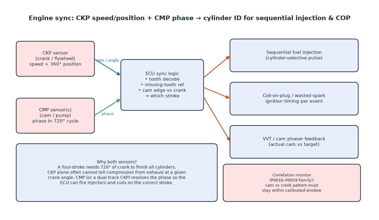
Why the ECU needs both sensors for sync
A spark-ignition four-stroke finishes all cylinders only after 720° of crank. CKP alone gives 360° position and speed. CMP (or an equivalent second track) resolves which revolution is which, so the ECU can:
- fire sequential injectors on the correct stroke;
- command coil-on-plug (or wasted-spark) events at the right time;
- read actual cam position for variable valve timing (VVT) phasers and close the phase loop.
Correlation monitors compare the cam edge(s) against the crank pattern. If the phase drifts outside a calibrated window — jumped belt or chain, stretched chain, stuck phaser, damaged tone ring — codes in the P0016–P0019 family set.
What goes wrong in the field
- Wrong air gap after a sensor or flywheel job — signal too weak or intermittent.
- Damaged or cracked reluctor / tone ring — missing or extra “teeth” in the decoded pattern (P0336 / P0341-type behaviour).
- Metallic debris stuck to the magnet, especially after clutch or starter work.
- Oil or coolant in the connector — common on cam-cover CMP sensors.
- Harness chafing on hot exhaust, turbo heat shields or sharp brackets.
- Jumped or stretched timing belt/chain — mechanical phase error with healthy sensors (correlation codes).
- Failed sensor — open coil, dead Hall IC, or intermittent internal fault.
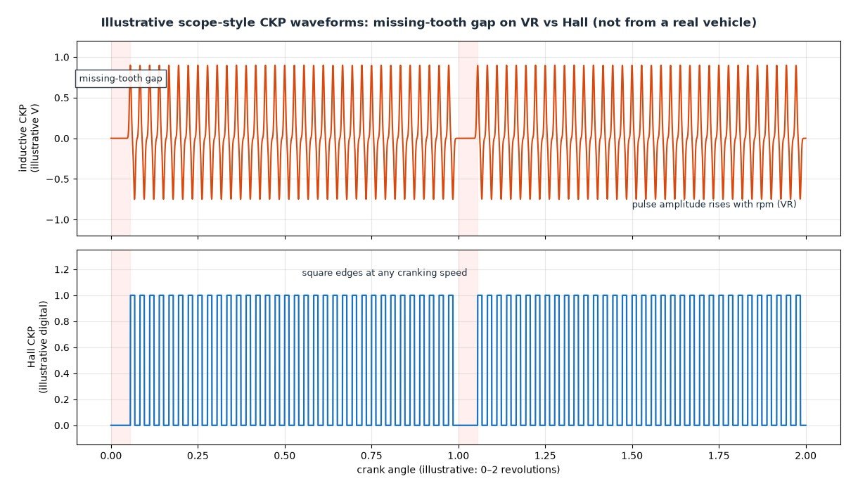
Practical diagnostics
- Read codes and freeze frame: circuit, range/performance, intermittent, or crank/cam correlation?
- Check connector fit, oil ingress, pin tension and harness routing near heat and moving parts.
- Verify air gap against the service specification; inspect the tone wheel for cracks, missing teeth and debris.
- Scope the CKP: look for a clean missing-tooth gap, stable amplitude (VR) or clean edges (Hall), and no dropouts under load or heat.
- Scope or compare CMP against CKP; confirm the cam edge lands in the expected crank window.
- Watch live rpm during cranking and running — rpm that drops to zero then returns often means an intermittent CKP.
- If correlation codes persist with good waveforms, check mechanical timing (belt/chain marks, stretched chain, phaser position).
A no-start with no rpm signal usually points to CKP or its wiring. An intermittent misfire that clears when cold and returns when hot often points to a failing sensor, oil in the connector or a cracked ring.
Related fault codes (DTCs)
Generic OBD-II (SAE J2012) codes for crankshaft and camshaft position sensor circuits and crank/cam correlation. Bank 1 contains cylinder 1; Sensor A is typically the intake (or sole) cam sensor and Sensor B the exhaust (or second) cam sensor where dual cams are fitted. Exact wording and enable conditions vary by manufacturer.
| Code | Meaning | Typical causes |
|---|---|---|
| P0016 | Crankshaft Position – Camshaft Position Correlation (Bank 1 Sensor A) | Timing belt/chain jumped or stretched, incorrect cam/crank timing after repair, damaged CKP or CMP tone wheel, wrong sensor air gap, wiring swapped or shorted, failed CKP/CMP sensor |
| P0017 | Crankshaft Position – Camshaft Position Correlation (Bank 1 Sensor B) | As P0016 on bank 1 cam sensor B (exhaust or second cam): jumped timing, damaged reluctor, sensor or wiring fault |
| P0018 | Crankshaft Position – Camshaft Position Correlation (Bank 2 Sensor A) | As P0016 on bank 2: jumped timing belt/chain, cam phaser stuck, damaged tone ring, sensor or wiring fault |
| P0019 | Crankshaft Position – Camshaft Position Correlation (Bank 2 Sensor B) | As P0017 on bank 2: cam/crank phase outside limits |
| P0335 | Crankshaft Position Sensor "A" Circuit | Open/short in CKP signal circuit, unplugged connector, failed sensor, damaged wiring near the engine |
| P0336 | Crankshaft Position Sensor "A" Circuit Range/Performance | Implausible tooth count or pattern: damaged or cracked reluctor/flywheel ring, wrong air gap, metallic debris, intermittent signal dropout |
| P0337 | Crankshaft Position Sensor "A" Circuit Low | Signal open or shorted to ground, failed sensor, poor ground |
| P0338 | Crankshaft Position Sensor "A" Circuit High | Signal shorted to voltage, open ground, failed sensor |
| P0339 | Crankshaft Position Sensor "A" Circuit Intermittent | Loose connector pins, chafed harness, oil or coolant in the connector, failing sensor, cracked tone wheel causing dropouts |
| P0340 | Camshaft Position Sensor "A" Circuit (Bank 1 or Single Sensor) | Open/short in CMP signal circuit, unplugged connector, failed sensor, wiring damage |
| P0341 | Camshaft Position Sensor "A" Circuit Range/Performance (Bank 1 or Single Sensor) | Implausible CMP pattern vs CKP: damaged cam tone wheel, wrong air gap, debris, intermittent signal, timing off |
| P0342 | Camshaft Position Sensor "A" Circuit Low (Bank 1 or Single Sensor) | CMP signal open or shorted to ground, failed sensor |
| P0343 | Camshaft Position Sensor "A" Circuit High (Bank 1 or Single Sensor) | CMP signal shorted to voltage, open ground, failed sensor |
| P0344 | Camshaft Position Sensor "A" Circuit Intermittent (Bank 1 or Single Sensor) | Loose pins, oil in connector, chafed harness near the cam cover, failing sensor |
| P0345 | Camshaft Position Sensor "A" Circuit (Bank 2) | Open/short in bank 2 CMP A circuit, unplugged connector, failed sensor |
| P0346 | Camshaft Position Sensor "A" Circuit Range/Performance (Bank 2) | Implausible bank 2 CMP A pattern: damaged tone wheel, air gap, debris, or timing issue |
| P0347 | Camshaft Position Sensor "A" Circuit Low (Bank 2) | Bank 2 CMP A signal open or shorted to ground, failed sensor |
| P0348 | Camshaft Position Sensor "A" Circuit High (Bank 2) | Bank 2 CMP A signal shorted to voltage, open ground, failed sensor |
| P0349 | Camshaft Position Sensor "A" Circuit Intermittent (Bank 2) | Loose connector or harness fault on bank 2 CMP A |
| P0365 | Camshaft Position Sensor "B" Circuit (Bank 1) | Open/short in CMP B (often exhaust cam) circuit on bank 1, unplugged connector, failed sensor |
| P0366 | Camshaft Position Sensor "B" Circuit Range/Performance (Bank 1) | Implausible CMP B pattern on bank 1: damaged tone wheel, wrong air gap, debris |
| P0367 | Camshaft Position Sensor "B" Circuit Low (Bank 1) | CMP B signal open or shorted to ground, failed sensor |
| P0368 | Camshaft Position Sensor "B" Circuit High (Bank 1) | CMP B signal shorted to voltage, open ground, failed sensor |
| P0369 | Camshaft Position Sensor "B" Circuit Intermittent (Bank 1) | Loose pins, oil in connector, chafed harness on bank 1 CMP B |
| P0390 | Camshaft Position Sensor "B" Circuit (Bank 2) | Open/short in bank 2 CMP B circuit, unplugged connector, failed sensor |
| P0391 | Camshaft Position Sensor "B" Circuit Range/Performance (Bank 2) | Implausible bank 2 CMP B pattern: damaged tone wheel, air gap, debris, timing issue |
| P0392 | Camshaft Position Sensor "B" Circuit Low (Bank 2) | Bank 2 CMP B signal open or shorted to ground, failed sensor |
| P0393 | Camshaft Position Sensor "B" Circuit High (Bank 2) | Bank 2 CMP B signal shorted to voltage, open ground, failed sensor |
| P0394 | Camshaft Position Sensor "B" Circuit Intermittent (Bank 2) | Loose connector or harness fault on bank 2 CMP B |
Cars, vans, trucks, agricultural machines and bikes
Passenger cars and light vans typically mount CKP on the crank pulley or flywheel and one or more CMP sensors on the cam cover — more sensors appear once dual VVT is fitted. Many diesels place CKP on the flywheel and CMP on the cam or high-pressure pump; sync is just as critical for injection timing. Heavy trucks and agricultural diesels follow the same principles at larger scale: flywheel rings, pump or cam sensors, and strict correlation monitors. Fuel-injected motorcycles often run a single CKP with wasted-spark ignition and a simpler or absent CMP; when a cam sensor is present, the same VR/Hall and air-gap rules apply.
What it means for tuning
Do not disable crank/cam correlation or sync monitors to “clear a code” — you hide a timing or sensor fault that can destroy the engine. Wrong CKP tooth offset or reference tooth in a calibration shifts ignition and injection relative to true TDC. After any timing belt/chain or tone-wheel repair, confirm sync with a scope or known-good correlation data before chasing power. Protect the hardware: correct air gap, clean connectors, and intact tone wheels matter more than any map change.
Summary
CKP gives speed and crank angle from a toothed wheel; CMP gives phase in the 720° cycle. Inductive sensors make AC voltage; Hall sensors make a supplied square wave. Missing-tooth gaps mark the crank reference. Correlation codes mean the cam and crank disagree — sensors, wiring or mechanical timing. Diagnose waveforms and timing marks before replacing parts.
Need a calibration that respects real crank/cam sync? Order your tuning file from ECUFileMarket.
One Response