
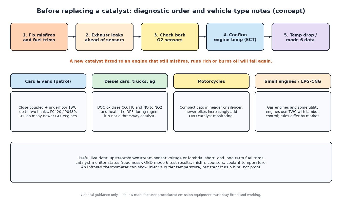
The catalytic converter is one of the most important parts of an exhaust system and one of the most misunderstood. It does not filter anything. It is a chemical reactor that depends on the engine control unit holding the mixture in a very narrow band, and it is watched by the ECU through its own diagnostic monitor. This article explains how a catalytic converter works, how the ECU looks after it and how catalyst efficiency monitoring decides when to store P0420, with notes for cars, trucks, agricultural machines and motorcycles.
What is inside a catalytic converter
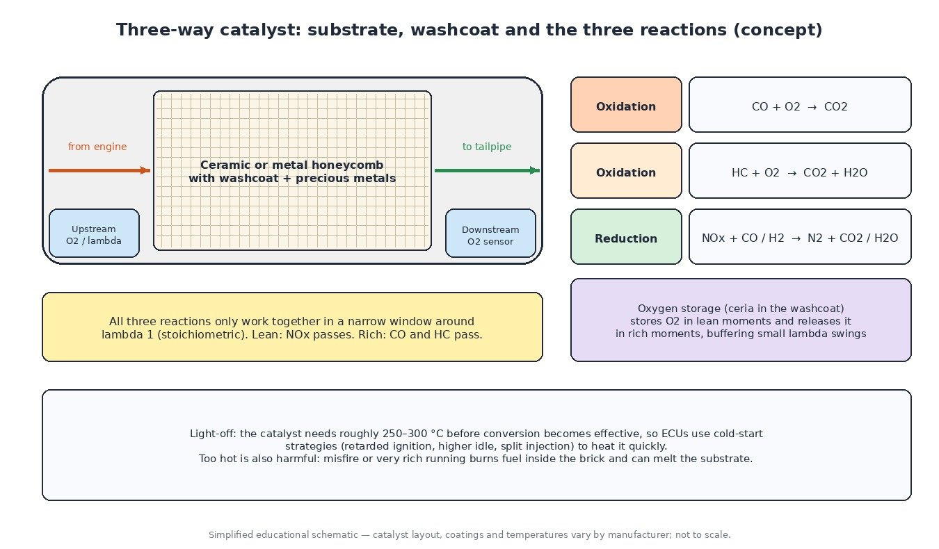
A catalyst consists of a ceramic or metal honeycomb substrate with thousands of thin channels. The channel walls carry a washcoat, a porous layer that greatly increases the surface area, and small amounts of precious metals such as platinum, palladium and rhodium. The washcoat also contains oxygen-storage materials, typically based on cerium oxide, which become important for the ECU’s monitoring later.
The substrate sits in a stainless housing, often with a close-coupled catalyst right after the exhaust manifold or turbo for fast warm-up, and a second underfloor catalyst further back on many petrol vehicles.
Three-way catalyst chemistry
A petrol three-way catalyst (TWC) treats three pollutants at once:
- Carbon monoxide (CO) is oxidised to carbon dioxide.
- Unburnt hydrocarbons (HC) are oxidised to carbon dioxide and water.
- Nitrogen oxides (NOx) are reduced to nitrogen, using CO and hydrogen in the exhaust as reducing agents.
Oxidation needs oxygen and reduction needs a lack of it, so all three reactions only work well together in a narrow window around lambda 1, the stoichiometric mixture. Slightly lean, and NOx slips through. Slightly rich, and CO and HC pass. The oxygen storage in the washcoat helps by absorbing oxygen during brief lean moments and releasing it during brief rich moments.
How the ECU looks after the catalyst
Closed-loop lambda control
The upstream oxygen sensor, narrowband or wideband, lets the ECU correct fuelling continuously so the mixture oscillates gently around lambda 1. Many systems also use the downstream sensor in a slower outer loop that fine-tunes the target of the front sensor, keeping the catalyst in its best working point as components age.
Light-off and cold start
A catalyst does very little until it reaches its light-off temperature, commonly cited at roughly 250 to 300 °C. Because most emissions on a test cycle are produced in the first minute after a cold start, ECUs run catalyst-heating strategies: retarded ignition, raised idle speed, and on direct-injection engines split or late injection. Some systems also use secondary air injection or electrically heated catalysts.
Overtemperature protection
Too much heat is just as harmful. Misfire sends unburnt fuel into the catalyst, where it burns inside the brick and can melt the substrate. The misfire monitor therefore distinguishes catalyst-damaging misfire rates and flashes the warning lamp. At high load, many petrol ECUs enrich the mixture to cool exhaust components, based on a modelled or measured exhaust temperature.
Catalyst efficiency monitoring
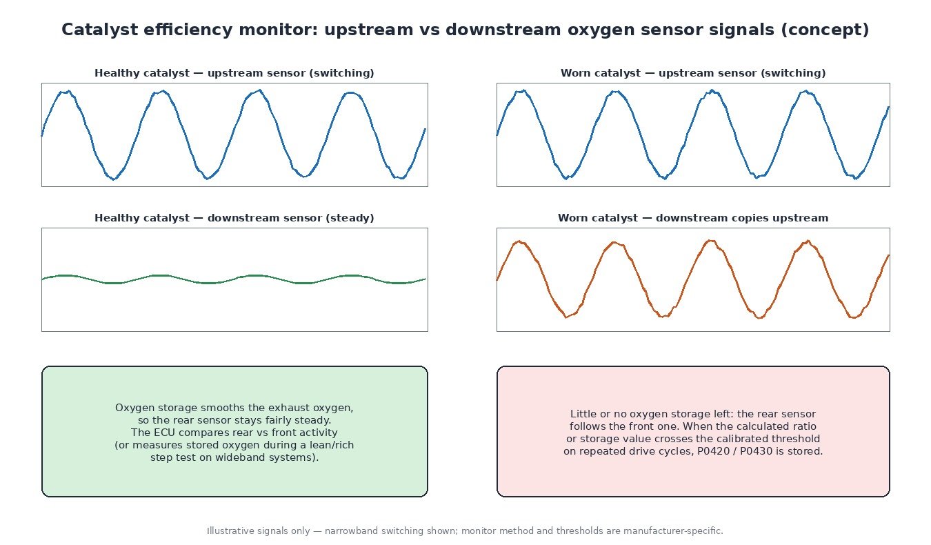
OBD regulations require the ECU to detect when the catalyst can no longer keep emissions within limits. Directly measuring conversion is not practical, so the monitor uses oxygen storage as an indicator. A healthy catalyst stores and releases oxygen, so the downstream sensor stays relatively steady while the front sensor switches. As the catalyst ages, storage falls and the rear sensor starts to copy the front one.
Narrowband systems typically compare the activity of the two signals, for example a ratio of switching or signal length. Wideband systems can command a defined lean and rich step and measure how long the rear sensor takes to react, which gives an oxygen storage value. The monitor runs only under stable conditions such as a warm engine and steady cruise, and a code is usually stored after the result fails on more than one drive cycle. The thresholds are set by each manufacturer.
Diesel oxidation catalysts
Diesels run lean, so a three-way catalyst cannot reduce NOx. Instead, a diesel oxidation catalyst (DOC) oxidises CO and HC, converts part of the NO to NO2, which helps passive soot oxidation in the particulate filter, and burns post-injected fuel to heat the DPF during active regeneration. NOx is handled separately by EGR and SCR. Trucks and agricultural machines with Stage V and Euro VI systems use the same DOC, DPF and SCR chain on a larger scale, and their ECUs monitor DOC performance through temperature rise across the catalyst.
Vehicle-type notes
Cars and vans use one or two TWCs per bank, with banks reported separately as P0420 and P0430. Many newer petrol direct-injection engines also carry a gasoline particulate filter. Trucks and agricultural machines are almost always diesel and rely on DOC monitoring and exhaust temperature sensors. Motorcycles use compact catalysts in the header or silencer, closed-loop lambda control is common on fuel-injected bikes, and newer models increasingly include OBD catalyst monitoring. Gas engines running on CNG or LPG also use three-way catalysts with lambda control.
What this means for calibration
Any change to fuelling, ignition or exhaust temperature affects the catalyst. Keeping lambda control, catalyst heating and component protection working as designed protects both the catalyst and the emission result. Catalysts, DPF, EGR and AdBlue/SCR are systems a calibration must work with, never remove.
Related fault codes (DTCs)
Generic OBD-II codes (SAE J2012). Wording and the exact sensor used vary by manufacturer.
| Code | Meaning | Typical causes |
|---|---|---|
| P0420 | Catalyst System Efficiency Below Threshold (Bank 1) | Aged or poisoned catalyst, exhaust leak ahead of the rear sensor, slow or biased downstream sensor, misfire or rich running history |
| P0421 | Warm Up Catalyst Efficiency Below Threshold (Bank 1) | Worn close-coupled catalyst, leak near the manifold, sensor fault |
| P0422 | Main Catalyst Efficiency Below Threshold (Bank 1) | Worn underfloor catalyst, exhaust leak, downstream sensor fault |
| P0423 | Heated Catalyst Efficiency Below Threshold (Bank 1) | Heated catalyst element or control fault, aged catalyst |
| P0424 | Heated Catalyst Temperature Below Threshold (Bank 1) | Catalyst heater circuit fault, catalyst not reaching temperature |
| P0425 | Catalyst Temperature Sensor (Bank 1) | Failed catalyst temperature sensor, wiring or connector fault |
| P0426 | Catalyst Temperature Sensor Range/Performance (Bank 1) | Implausible sensor reading, sensor drift, exhaust leak near the sensor |
| P0427 | Catalyst Temperature Sensor Circuit Low (Bank 1) | Short to ground, damaged sensor |
| P0428 | Catalyst Temperature Sensor Circuit High (Bank 1) | Open circuit, short to voltage, unplugged sensor |
| P0430 | Catalyst System Efficiency Below Threshold (Bank 2) | Same causes as P0420, on the bank 2 catalyst |
| P0431 | Warm Up Catalyst Efficiency Below Threshold (Bank 2) | Worn bank 2 close-coupled catalyst, leak, sensor fault |
| P0136 | O2 Sensor Circuit (Bank 1 Sensor 2) | Downstream sensor or wiring fault |
| P0137 | O2 Sensor Circuit Low Voltage (Bank 1 Sensor 2) | Exhaust leak pulling in air, short to ground, failed sensor |
| P0138 | O2 Sensor Circuit High Voltage (Bank 1 Sensor 2) | Short to voltage, sensor fault, very rich running |
| P0139 | O2 Sensor Circuit Slow Response (Bank 1 Sensor 2) | Aged or contaminated downstream sensor |
| P0141 | O2 Sensor Heater Circuit (Bank 1 Sensor 2) | Failed heater element, fuse, wiring or connector |
| P2096 | Post Catalyst Fuel Trim System Too Lean (Bank 1) | Exhaust leak, intake leak, low fuel pressure, downstream sensor bias |
| P2097 | Post Catalyst Fuel Trim System Too Rich (Bank 1) | Leaking injector, high fuel pressure, upstream sensor bias, purge fault |
| P2270 | O2 Sensor Signal Stuck Lean (Bank 1 Sensor 2) | Exhaust leak, failed sensor, wiring fault |
| P2271 | O2 Sensor Signal Stuck Rich (Bank 1 Sensor 2) | Rich running, sensor contamination, failed sensor |
| P0300 | Random/Multiple Cylinder Misfire Detected | Ignition, injection, compression or air leaks; unburnt fuel overheats and damages the catalyst |
| P0171 | System Too Lean (Bank 1) | Intake or vacuum leak, MAF contamination, low fuel pressure |
| P0172 | System Too Rich (Bank 1) | Leaking injectors, high fuel pressure, MAF or ECT fault |
| P0544 | Exhaust Gas Temperature Sensor Circuit (Bank 1 Sensor 1) | EGT sensor or wiring fault; affects catalyst and DPF temperature control on diesels |
Closing
A catalytic converter is only as healthy as the engine in front of it. Understanding the chemistry, the lambda window and the monitor makes P0420 diagnosis logical instead of expensive guesswork.
Need a custom engineered ECU or TCU file built from your original read? Upload your file at ECUFileMarket.
2 Responses