
The engine ECU on a modern vehicle never works alone. It shares torque requests with the transmission, receives wheel speeds from the ABS, sends coolant temperature to the instrument cluster and answers the diagnostic tool over a pair of twisted wires. That network is CAN, the Controller Area Network. Understanding it makes communication faults easier to fix and explains why a stable connection matters before any ECU is read or written through the OBD socket.
How CAN sends a bit
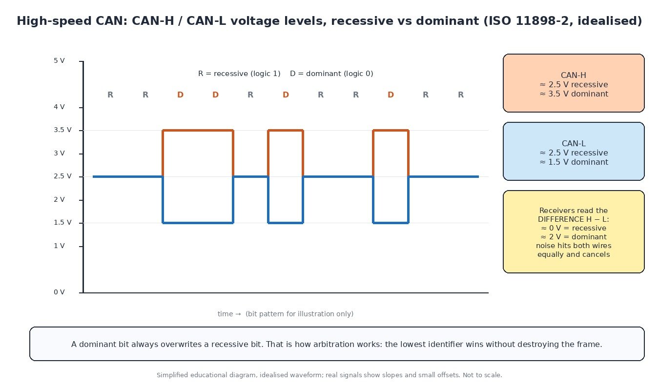
High-speed CAN (ISO 11898-2) uses two wires, CAN-H and CAN-L, twisted together. In the idle, recessive state both sit at about 2.5 V, so the difference between them is roughly zero. To send a dominant bit, the transmitting module pulls CAN-H up to about 3.5 V and CAN-L down to about 1.5 V, giving a difference of about 2 V. Receivers only look at that difference. Noise usually hits both wires equally and cancels out.
Each end of the bus carries a 120 Ω termination resistor. They stop reflections, and because the two resistors sit in parallel, a healthy bus measures about 60 Ω between CAN-H and CAN-L.
Arbitration: who gets to talk
CAN has no master. Any module can start transmitting when the bus is free, and every frame begins with an identifier: 11 bits in the standard format, 29 bits in the extended format. If two start at once, each compares the bus with what it sends. A dominant bit overwrites a recessive one, so the module that sent a recessive bit and reads back a dominant one stops and tries again later. The lower identifier always wins, and the winning frame is not damaged.
Every frame also carries a CRC and an acknowledge slot. A module that keeps causing errors eventually switches itself off the bus (“bus-off”), so one faulty node cannot block the network forever.
Several buses, one gateway
A car rarely has just one CAN bus. Powertrain and chassis modules commonly share a high-speed bus at 500 kbit/s, while body and comfort functions may use a slower bus. Older vehicles used fault-tolerant low-speed CAN (ISO 11898-3, up to 125 kbit/s), which can keep working on a single wire after a fault and terminates differently, so the 60 Ω rule does not apply to it. Simple devices such as window motors or a smart alternator often use LIN, a slow single-wire sub-bus. Some premium platforms use FlexRay for chassis functions, and newer ones add CAN FD (up to 64 data bytes per frame, faster data phase) and Ethernet.

A gateway joins the buses and forwards only the messages each one needs. On many vehicles the OBD socket connects to the gateway, not directly to the powertrain bus.
How diagnostics travel
OBD-II and EOBD over CAN follow ISO 15765-4, using pins 6 (CAN-H) and 14 (CAN-L) of the diagnostic socket; in the US, CAN has been required for OBD-II from the 2008 model year. A scan tool sends a functional request on identifier 7DF, and emissions-related ECUs answer on 7E8 to 7EF.
Workshop tools and programming tools go further with UDS (ISO 14229). Services such as Read DTC Information, Read Data By Identifier, Security Access, Request Download and Transfer Data are the building blocks of reading, coding and flashing an ECU or TCU. Newer platforms also run them over Ethernet (DoIP, ISO 13400).
Trucks, tractors and motorbikes
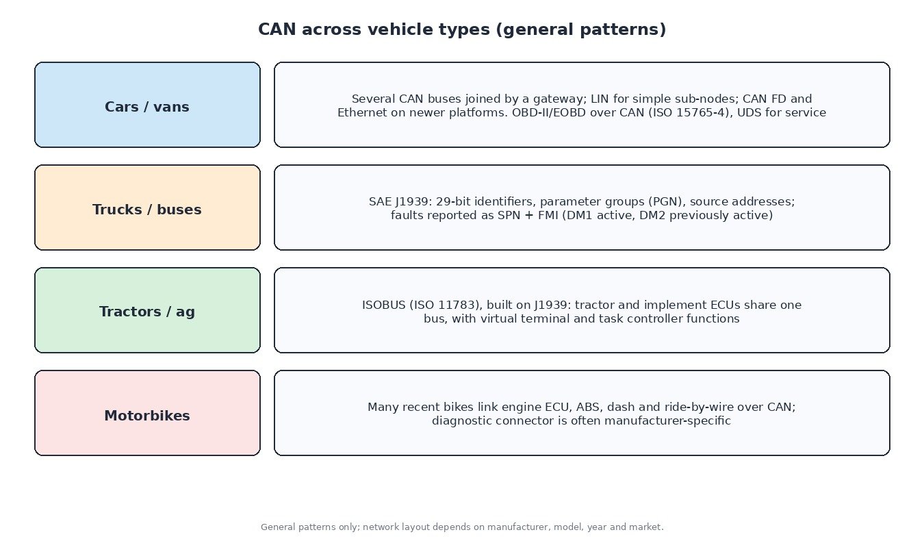
Heavy-duty vehicles use SAE J1939, built on 29-bit identifiers that carry a priority, a parameter group number (PGN) and the sender’s source address, traditionally at 250 kbit/s. Faults are reported as an SPN (which parameter) plus an FMI (how it failed), broadcast in DM1 for active faults and DM2 for previously active ones, rather than as P or U codes. Agricultural machines use ISOBUS (ISO 11783), which builds on J1939 so that tractor and implement ECUs can share one bus with a virtual terminal and task controller. Many modern motorbikes link the engine ECU, ABS, dashboard and ride-by-wire over CAN.
Practical diagnostics
- Power and ground first. A module with a weak supply drops off the bus and others log “lost communication”. Check battery, fuses and grounds first.
- Resistance with the battery disconnected. About 60 Ω between CAN-H and CAN-L is healthy, about 120 Ω means one termination or one leg of the bus is open, and near 0 Ω means the two wires are shorted together.
- Voltage and scope. With the ignition on, both lines should rest near 2.5 V. A two-channel scope should show CAN-H and CAN-L as clean mirror images; a line stuck at 0 V or battery voltage points to a short.
- Unplug one module at a time. If the bus recovers when a particular module is disconnected, that module or its harness branch is pulling the network down.
Why it matters for ECU work
Reading or writing an ECU over OBD sends thousands of UDS messages across this network. A voltage dip, a security gateway that needs authorisation or an aftermarket device on the bus can interrupt the session. Use a battery support unit, unplug trackers and add-ons, and confirm the bus is healthy first. If OBD access is blocked or unreliable, a bench or boot connection is often safer.
Related fault codes (DTCs)
Generic OBD-II codes (SAE J2012) commonly linked to CAN network faults. Wording varies by manufacturer and J1939 vehicles use SPN/FMI instead, so read every module.
| Code | Meaning | Typical causes |
|---|---|---|
| U0001 | High Speed CAN Communication Bus | CAN-H or CAN-L open or shorted, missing termination, a faulty module holding the bus |
| U0073 | Control Module Communication Bus “A” Off | Module went bus-off after repeated errors: wiring damage, short, water in a connector, module fault |
| U0100 | Lost Communication With ECM/PCM “A” | ECU power, ground or fuse fault, open CAN wires at the ECU, low voltage while cranking |
| U0101 | Lost Communication With TCM | TCU supply or ground, connector corrosion, CAN wiring to the TCU, TCU fault |
| U0121 | Lost Communication With Anti-Lock Brake System (ABS) Control Module | ABS module fuse or ground, damaged harness, water ingress, module fault |
| U0140 | Lost Communication With Body Control Module | BCM supply or ground, body bus or gateway wiring, module not waking |
| U0155 | Lost Communication With Instrument Panel Cluster (IPC) Control Module | Cluster power or ground, connector or wiring fault; on some cars the cluster holds a termination or gateway |
| U0401 | Invalid Data Received From ECM/PCM “A” | Messages arrive but fail checks: ECU internal fault, mismatched software or coding after replacement |
| P0600 | Serial Communication Link | Communication fault seen by the ECU; check power, grounds and the bus before condemning it |
| P0562 | System Voltage Low | Weak battery, charging fault or poor ground; often sets U-codes in many modules at once |
Closing
CAN faults show up in many modules at once. Start with power and grounds, measure, scope, then isolate one module at a time.
Need an engineered ECU or TCU file for a car, van, truck, tractor or bike? Upload your original read at ECUFileMarket.