
Exhaust gas temperature (EGT) is one of the most important numbers an engine control unit (ECU) watches, even though most drivers never see it. Turbochargers, catalysts, particulate filters and exhaust valves all have temperature limits, and modern emissions systems only work inside a specific temperature window. EGT sensors give the ECU that information. This guide explains how the sensors work, where they are fitted, what the ECU does with the signal and how to diagnose the common fault codes on cars, trucks, tractors and bikes.
Why exhaust temperature matters
Exhaust gas leaving the cylinders carries a large share of the fuel’s energy as heat. Too much heat cracks turbine housings, erodes turbine blades, burns exhaust valves and ages catalysts. Too little heat is also a problem: an oxidation catalyst does not light off, a diesel particulate filter (DPF) cannot regenerate, and an SCR (selective catalytic reduction) system cannot safely dose AdBlue/DEF. So the ECU needs to know the temperature at several points, both to protect hardware and to run the emissions strategy correctly.
Where the sensors are fitted
A simple petrol turbo engine may have a single sensor before the turbine, or none at all and rely purely on a temperature model. A Euro 6 diesel car or a Stage V tractor often has three or four:
- Pre-turbine – protects the turbocharger and exhaust manifold.
- DOC inlet – confirms the diesel oxidation catalyst is hot enough to light off before a regeneration starts.
- DPF inlet – lets the ECU hold the filter at regeneration temperature without overshooting.
- SCR inlet – AdBlue dosing is only enabled above a minimum catalyst temperature, otherwise urea deposits can form.
How an EGT sensor works
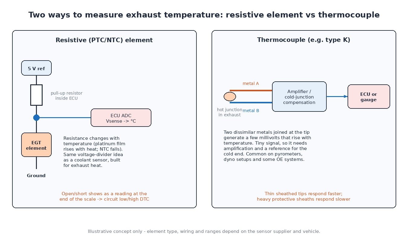
Most original-equipment EGT sensors are resistive: a temperature-dependent element sits in a sealed metal tip in the gas stream. Platinum-film elements increase their resistance as they heat up (PTC); some older or specific designs use NTC material that does the opposite. The ECU feeds the sensor through a pull-up resistor and reads the resulting voltage, exactly like a coolant sensor but built for far higher temperatures. Because the ECU knows the characteristic curve, it converts that voltage to degrees.
The alternative is a thermocouple. Two dissimilar metals joined at the tip produce a small voltage, in the millivolt range, that grows with temperature. That signal is too small to read directly, so it goes through an amplifier with cold-junction compensation. Thermocouples (type K is common) are widely used in aftermarket pyrometers and dyno setups, and some OE systems use them with a separate amplifier module.
Response time depends on the tip design. A thin exposed tip reacts quickly; a heavy protective sheath survives longer but lags behind fast temperature changes. That is why logged EGT often trails a sudden load step by a second or more.
What the ECU does with the signal
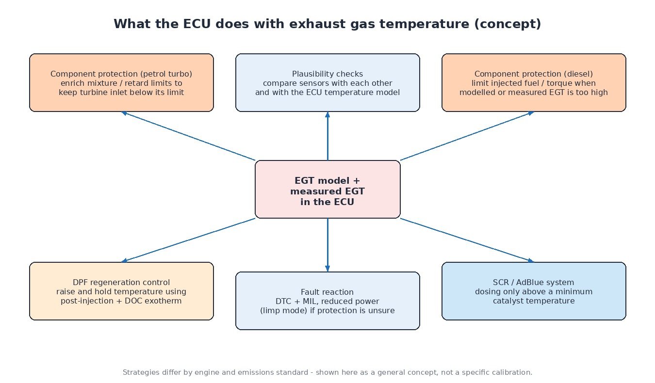
- Component protection on petrol turbo engines – when the modelled or measured temperature approaches the limit, the ECU enriches the mixture to cool the exhaust and may cap boost or ignition advance.
- Component protection on diesels – diesels run lean, so the ECU protects the turbo mainly by limiting injected fuel and torque.
- DPF regeneration – late post-injection raises hydrocarbons that burn in the DOC; the ECU uses DOC and DPF inlet readings to raise and hold the target temperature.
- SCR enable – dosing starts only once the catalyst inlet is warm enough.
- Plausibility – after a cold soak all sensors should read close to each other; under load they should follow the ECU’s temperature model.
Diagnosing EGT faults
- Read codes and freeze frame, noting which bank and sensor number is flagged. Sensor numbering follows the gas flow, but positions differ by engine, so check service data.
- Do a cold-soak comparison. After the vehicle has stood overnight, all EGT readings at key-on should be near ambient. One sensor far away from the others points to that sensor or its wiring.
- Check the circuit. An open circuit or short shows as a reading at the end of the scale. Measure the sensor resistance and compare it with the specification, then check the harness, which often runs close to hot exhaust parts and melts or chafes.
- Look at live data under load. A sensor that is slow, stuck or reads far below the others during a road test is likely to set a range/performance code.
- Treat over-temperature codes seriously. A real high EGT can come from a restricted exhaust, a blocked DPF, leaking injectors, a boost leak or incorrect fuelling. Confirm the reading with a second sensor or a pyrometer before replacing parts.
Trucks, agricultural machines and bikes
Heavy trucks and Stage IV/V tractors use the same layout as diesel cars, usually with an extra sensor around the SCR and often longer harnesses that suffer from vibration and heat. Agricultural machines also spend long periods at high load, so EGT protection derates are common under PTO work. Motorcycles rarely have dedicated EGT sensors; most rely on a temperature model, although some racing and turbo applications add a pyrometer for logging.
Related fault codes (DTCs)
Generic SAE J2012 codes. Bank and sensor locations depend on the engine, so always confirm with service data.
| Code | Meaning | Typical causes |
|---|---|---|
| P0544 | Exhaust Gas Temperature Sensor Circuit Bank 1 Sensor 1 | Sensor, connector or harness fault |
| P0545 | Exhaust Gas Temperature Sensor Circuit Low Bank 1 Sensor 1 | Short to ground, failed element |
| P0546 | Exhaust Gas Temperature Sensor Circuit High Bank 1 Sensor 1 | Open circuit, unplugged connector, heat-damaged wiring |
| P0547 | Exhaust Gas Temperature Sensor Circuit Bank 2 Sensor 1 | Sensor or wiring fault (bank 2) |
| P0548 | Exhaust Gas Temperature Sensor Circuit Low Bank 2 Sensor 1 | Short to ground, failed element |
| P0549 | Exhaust Gas Temperature Sensor Circuit High Bank 2 Sensor 1 | Open circuit, connector, wiring |
| P2031 | Exhaust Gas Temperature Sensor Circuit Bank 1 Sensor 2 | Sensor or harness fault |
| P2032 | Exhaust Gas Temperature Sensor Circuit Low Bank 1 Sensor 2 | Short to ground, failed element |
| P2033 | Exhaust Gas Temperature Sensor Circuit High Bank 1 Sensor 2 | Open circuit, melted wiring, corroded pins |
| P2080 | Exhaust Gas Temperature Sensor Circuit Range/Performance Bank 1 Sensor 1 | Slow or drifting sensor, implausible vs model or other sensors |
| P2081 | Exhaust Gas Temperature Sensor Circuit Intermittent Bank 1 Sensor 1 | Loose pin, chafed harness |
| P2084 | Exhaust Gas Temperature Sensor Circuit Range/Performance Bank 1 Sensor 2 | Drifting sensor, exhaust leak near sensor |
| P2428 | Exhaust Gas Temperature Too High Bank 1 | Restricted exhaust or DPF, fuelling fault, boost leak, faulty sensor |
| P2429 | Exhaust Gas Temperature Too High Bank 2 | As P2428, bank 2 |
What it means for tuning
More fuel and more boost mean more heat, so EGT is one of the main limits on any remap. A good calibration keeps the factory temperature model and protection active and stays inside safe limits, especially on engines that tow, work under PTO load or run long motorway climbs. Raising or removing EGT protection to hide a problem is how turbos and pistons fail. Log EGT before and after tuning, and fix sensor or exhaust faults first.
Want a file that respects EGT limits and component protection? Order your tuning file from ECUFileMarket.