
Every liquid-cooled engine dumps combustion heat into a closed coolant circuit. The engine control unit (ECU) needs to know how hot that coolant is, because cold starts, warm-up, fan request, idle speed and several enable conditions all depend on it. The sensor that reports this is the engine coolant temperature (ECT) sensor – almost always an NTC thermistor screwed into the thermostat housing or a nearby jacket. Here is how the cooling hardware, the sensor and the ECU strategies fit together, and how to diagnose the common codes.
The cooling circuit in brief
- Water jackets in the block and cylinder head pick up heat from the combustion chambers and exhaust ports.
- Water pump (belt-driven or electric) circulates coolant through those jackets.
- Thermostat stays closed when the engine is cold so coolant recirculates through a short bypass and warms up quickly; once the wax element reaches its calibrated opening temperature, flow opens to the radiator.
- Radiator rejects heat to the air; an electric fan (or viscous clutch fan on some trucks) boosts airflow when vehicle speed alone is not enough.
- Expansion / pressure tank absorbs volume change and holds system pressure so the boiling point stays above ambient.
- ECT sensor sits where it sees representative jacket or thermostat-housing temperature and reports it to the ECU.
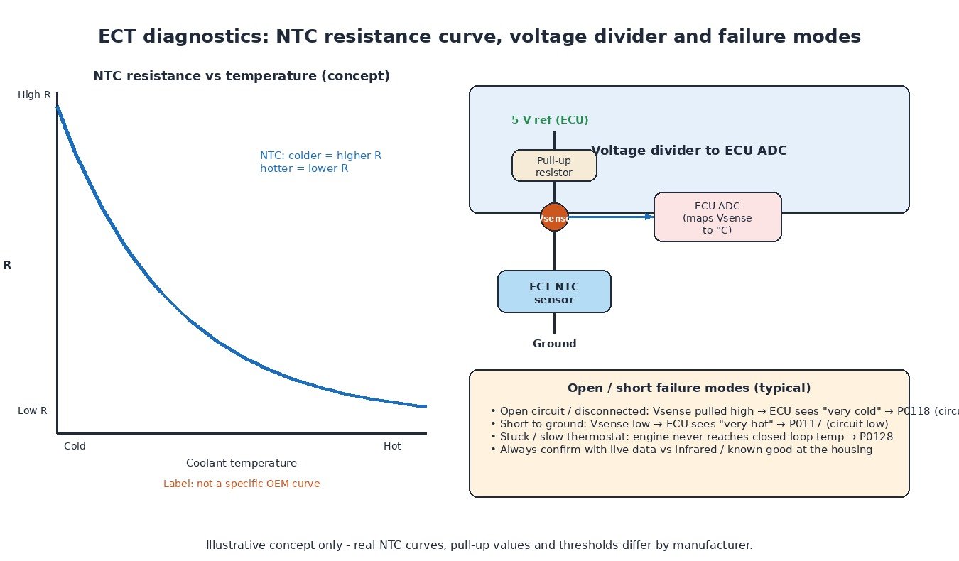
How an NTC ECT sensor works
NTC means negative temperature coefficient: as coolant temperature rises, the sensor resistance falls. Inside the ECU a pull-up resistor and the NTC form a voltage divider. The analogue-to-digital converter (ADC) reads the sense voltage and a look-up table converts it to degrees. Cold coolant means high resistance and a high sense voltage; hot coolant means low resistance and a low sense voltage. That is why an open circuit often looks like an extremely cold reading, and a short to ground looks extremely hot.
What the ECU does with coolant temperature
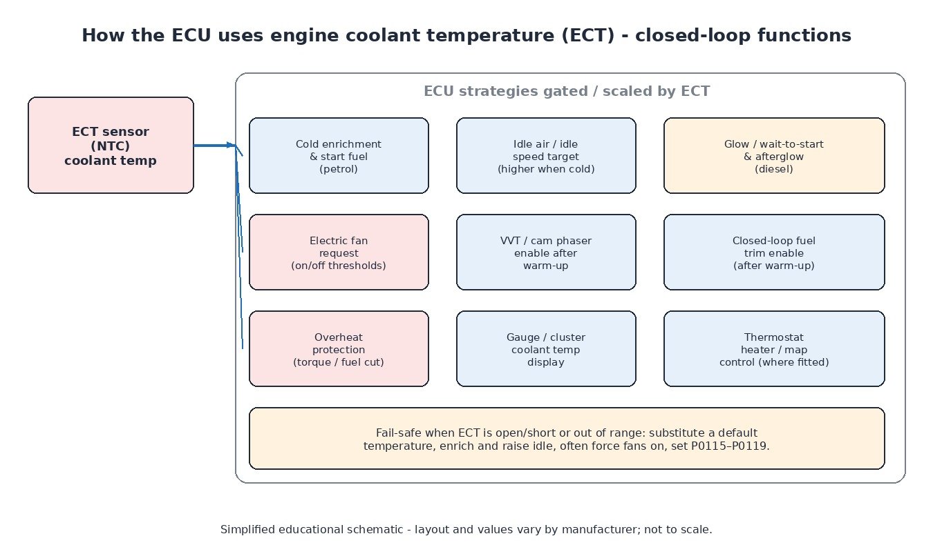
ECT is not only a gauge input. The ECU uses it for several closed-loop and enable strategies:
- Cold enrichment and start fuel on petrol engines – more fuel while walls and oil are cold.
- Idle air / idle speed target – a higher idle when cold, then a smooth drop as temperature rises.
- Electric fan request – fan(s) switch on and off at calibrated thresholds, sometimes with hysteresis and AC pressure as an extra input.
- Glow / wait-to-start and afterglow on diesels – longer glow when cold; afterglow may continue briefly after start.
- VVT / cam phaser enable – many engines keep the phaser locked until oil and coolant are warm enough.
- Closed-loop fuel trim enable – lambda feedback often waits until the engine is out of cold enrichment.
- Overheat protection – torque or fuel limiting, and in extreme cases a controlled shutdown strategy, if temperature exceeds a hard limit.
Symptoms of cooling and ECT faults
Typical signs include a warning lamp with temperature-circuit codes, a gauge that sits on cold or pegs hot, electric fans that never run or run continuously, hard cold starts, unstable warm-up idle, slow warm-up (stuck-open thermostat) or overheating under load (stuck-closed thermostat, failed pump, clogged radiator, failed fan). Always separate a real thermal problem from a sensor or wiring problem before replacing parts.
Diagnostics that find the real fault
- Read codes and freeze frame. Note circuit low, circuit high, range/performance, insufficient temperature for closed loop, or coolant over-temperature.
- Compare live ECT with a known reference. Key on, cold engine: ECT should roughly match ambient. During warm-up it should rise smoothly. An infrared thermometer or a second probe at the housing helps confirm whether the sensor or the cooling system is wrong.
- Check the thermostat behaviour. If the upper radiator hose stays cold for a long time after start, the thermostat may be stuck closed; if it gets hot almost immediately and the cabin heater is weak, it may be stuck open (P0128 territory on many petrol cars).
- Test the sensor and wiring. Measure NTC resistance against the service chart at known temperatures, check the 5 V reference / pull-up and ground at the connector, and look for oil or coolant in the plug.
- Command and observe the fan. Use the actuator test if available; confirm relay click, power and ground at the fan, and that the ECU request matches live data.
- Inspect the mechanical side. Coolant level, air locks after a refill, degraded coolant, blocked radiator fins, slipping belt (mechanical pump), and electric pump operation where fitted.
Cars, vans, trucks, agricultural machines and bikes
Passenger cars and light vans use the layout above almost universally, often with dual fans or a PWM fan module. Heavy trucks and many agricultural diesels add large mechanical or viscous fans, multiple thermostats and sometimes charged-air coolers that are separate from the jacket circuit; ECT still gates glow, idle and protection strategies. Liquid-cooled motorcycles place a compact radiator and electric fan up front, with the ECT sensor in the head or thermostat housing and the same NTC-to-ECU principle.
Related fault codes (DTCs)
Generic SAE J2012 codes; manufacturer-specific codes and dual-sensor (“ECT 1 / ECT 2”) layouts vary, so confirm with service data.
| Code | Meaning | Typical causes |
|---|---|---|
| P0115 | Engine Coolant Temperature Sensor 1 Circuit | General ECT circuit fault, connector, wiring, sensor |
| P0116 | Engine Coolant Temperature Sensor 1 Circuit Range/Performance | Implausible reading vs other temps, sticking thermostat, contaminated sensor |
| P0117 | Engine Coolant Temperature Sensor 1 Circuit Low | Short to ground, failed sensor (reads very hot) |
| P0118 | Engine Coolant Temperature Sensor 1 Circuit High | Open circuit, disconnected connector, failed sensor (reads very cold) |
| P0119 | Engine Coolant Temperature Sensor 1 Circuit Intermittent | Loose pin, chafed harness, intermittent open/short |
| P0125 | Insufficient Coolant Temperature for Closed Loop Fuel Control | Stuck-open thermostat, low coolant, ECT bias, very short trips |
| P0128 | Coolant Thermostat (Coolant Temperature Below Thermostat Regulating Temperature) | Thermostat stuck open or opening too early, low coolant |
| P0217 | Engine Coolant Over-Temperature Condition | Low coolant, failed pump, stuck-closed thermostat, failed fan, clogged radiator |
| P0480 | Fan 1 Control Circuit | Fan relay, wiring, ECU driver, fan motor |
| P0481 | Fan 2 Control Circuit | Second fan/relay circuit fault |
| P0482 | Fan 3 Control Circuit | Third fan/relay circuit fault (where fitted) |
| P0483 | Fan Rationality Check | Fan command vs feedback/implausible operation |
What it means for tuning
Warm-up enrichment, fan thresholds and temperature-based limiters are part of a calibration, but they exist to protect the engine and to meet emissions during warm-up. A remap must not disable overheat protection or invent substitute temperatures to hide a cooling fault. Fix thermostat, pump, fan and sensor issues first; then calibrate with logged ECT behaviour that matches the real thermal state of the engine.
Need a calibration that respects temperature protection and warm-up strategies? Browse the tuning file catalogue at ECUFileMarket.