
The manifold absolute pressure (MAP) sensor tells the engine control unit how much pressure sits in the intake manifold at any moment. On a naturally aspirated petrol engine that is mostly vacuum; on a turbo diesel van or truck it is boost. Combined with rpm and air temperature, that number lets the ECU calculate cylinder air charge, set fuel quantity and close the loop on turbo boost. Here is how the sensor works, how the ECU uses it, what fails and what it means for diagnostics and tuning.
Absolute, gauge and barometric pressure
Pressure can be measured against two different zero points. Gauge pressure is measured against the atmosphere around you: a tyre gauge or a dashboard boost gauge reads zero with the engine off. Absolute pressure is measured against a perfect vacuum. With the engine stopped, an absolute sensor reads whatever the atmosphere is pushing at that place and time — around 101 kPa at sea level on a standard day, and noticeably less at altitude.
The relationship is simple: absolute pressure = gauge pressure + barometric pressure. ECUs use absolute values because air density depends on absolute pressure.
Barometric pressure (BARO) is the ambient pressure outside the engine. It comes from a sensor on the ECU board or is learned from the MAP sensor at key-on.
How a piezoresistive MAP sensor works
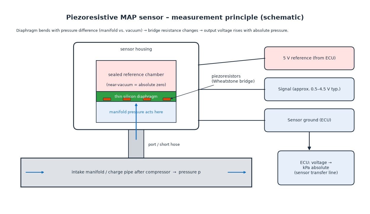
Most modern MAP and boost sensors are built around a small silicon chip. Part of the chip is etched very thin to form a diaphragm. Underneath or above it is a sealed chamber containing a near-vacuum — the “absolute” reference. Manifold pressure acts on the other side of the diaphragm, so the diaphragm bends in proportion to the absolute pressure.
Resistors diffused into the silicon change resistance when they are strained. This is the piezoresistive effect. Four of them are wired as a Wheatstone bridge so that the tiny resistance change becomes a measurable voltage.
Three wires (or four)
A typical sensor has a 5 V reference supplied by the ECU, a sensor ground back to the ECU and a signal wire. The output is ratiometric: it is a fraction of the reference voltage, commonly spanning roughly 0.5 V to 4.5 V across the sensor’s range so the ECU can tell a real reading from a short or an open circuit. A TMAP adds an air-temperature thermistor on a fourth wire. Each sensor has its own measuring range — 1-bar, 2.5-bar and 3-bar absolute versions are common — and the ECU must know the matching transfer line (offset and slope).
Where the sensor sits
On a naturally aspirated engine the MAP sensor reads the plenum after the throttle, mounted directly or via a short hose. On turbocharged engines there are usually two pressure measurements: a boost pressure sensor in the charge pipe or manifold after the intercooler, and sometimes a second sensor before the throttle. Diesel cars, vans, trucks and tractors almost always carry a charge-air pressure sensor, even when a MAF is fitted.
Motorcycles and small engines often rely on MAP because there is no room for a MAF. On single-cylinder engines the pressure pulses with every intake stroke, so the ECU samples it at a defined crank angle.
Speed-density: turning pressure into air charge
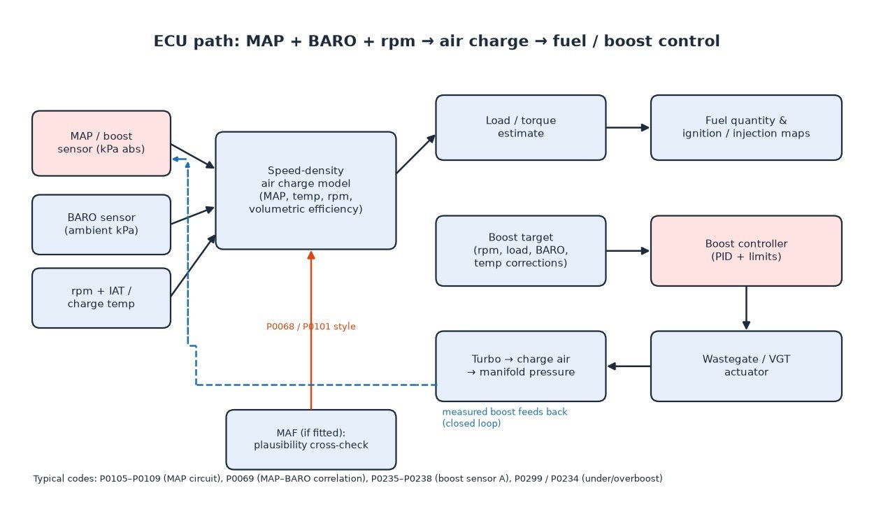
Without a MAF, the ECU calculates air mass using the speed-density method. The ideal gas law says the mass of air in a known volume depends on its pressure and temperature. The ECU knows displacement per cylinder, measures pressure and temperature, and applies a volumetric efficiency (VE) table — a map over rpm and load describing how well the engine actually fills its cylinders compared with the theory.
The result is an air charge per stroke, which becomes the load value used for fuel quantity, ignition timing and torque estimation. Engines with a MAF often run a pressure-based model in parallel; a large disagreement can set a correlation code such as P0068.
Boost sensing and closed-loop boost control
On a turbo engine the pressure sensor is the feedback signal for boost control. The ECU builds a boost target from rpm, requested torque, BARO and temperatures, compares it with measured pressure and drives the wastegate or VGT actuator through a controller with limits. Sustained deviation sets overboost (P0234) or underboost (P0299) and usually reduced power.
BARO matters here too. At altitude the turbo must spin faster for the same absolute pressure, so calibrations lower the target to protect it. On diesel trucks and agricultural machines the boost signal also feeds the smoke limiter, which caps fuel until enough air is present.
Common failures
- Hose and port problems: a split, collapsed or disconnected sensor hose makes the sensor read near atmospheric. On a speed-density engine that means the ECU thinks it is under high load and over-fuels at idle.
- Contamination: oil mist from crankcase ventilation and soot from EGR coat the sensor port on many diesels, slowing or freezing the reading.
- Charge-air leaks: a loose intercooler clamp or cracked hose lets boost escape; the sensor is right, but boost misses target.
- 5 V reference faults: several sensors often share one 5 V supply. A short in any of them can pull the reference down and set codes on sensors that are not faulty.
- Wiring: corrosion, heat damage and loose pins cause low, high or intermittent codes.
A practical diagnostic approach
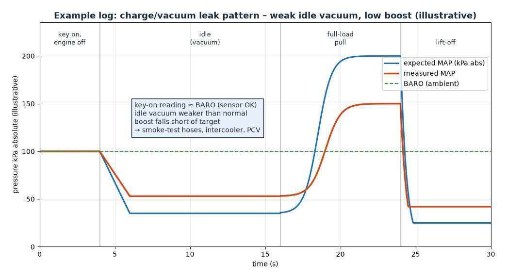
- Key on, engine off: MAP should read the same as BARO, or a local weather reference corrected for altitude. A clear offset points to the sensor or its circuit — this is exactly what P0069 checks.
- Idle: a healthy naturally aspirated petrol engine shows strong vacuum, well below BARO. Weak vacuum suggests a leak, timing problem or blocked hose.
- Snap and load test: the reading should drop quickly on throttle closure and rise smoothly under load. A flat line means the sensor is not seeing the manifold.
- Electrical checks: back-probe for the 5 V reference, a clean ground and a signal that moves. With the sensor removed, a hand vacuum/pressure pump should produce a smooth voltage change.
- Leak test: smoke-test the intake or pressure-test the charge-air system before replacing parts.
Related fault codes (DTCs)
Generic OBD-II (SAE J2012) codes related to manifold absolute pressure and barometric pressure sensing, turbo/supercharger boost sensors, MAP/BARO and MAP/MAF/throttle correlation, and the boost deviation codes a faulty pressure signal can trigger. Exact wording and enable conditions vary by manufacturer.
| Code | Meaning | Typical causes |
|---|---|---|
| P0068 | MAP/MAF – Throttle Position Correlation | MAP, MAF and throttle position disagree: intake/charge-air leak, sticking throttle, contaminated MAF, faulty or blocked MAP sensor |
| P0069 | Manifold Absolute Pressure – Barometric Pressure Correlation | MAP and BARO readings differ with engine stopped or at low load: drifting MAP or BARO sensor, blocked or wet sensor port, wiring/5 V reference fault |
| P0105 | Manifold Absolute Pressure/Barometric Pressure Circuit | Open or short in MAP signal, 5 V reference or ground circuit, unplugged connector, failed sensor |
| P0106 | Manifold Absolute Pressure/Barometric Pressure Circuit Range/Performance | Reading implausible for rpm/throttle/load: split or disconnected sensor hose, oily or sooted sensor, intake or charge-air leak, sensor drift |
| P0107 | Manifold Absolute Pressure/Barometric Pressure Circuit Low | Signal or 5 V reference open/shorted to ground, shared 5 V reference pulled down by another sensor, failed sensor |
| P0108 | Manifold Absolute Pressure/Barometric Pressure Circuit High | Signal shorted to voltage, open sensor ground, failed sensor; on some engines a real overpressure event |
| P0109 | Manifold Absolute Pressure/Barometric Pressure Circuit Intermittent | Loose or corroded connector pins, chafed harness, intermittent ground |
| P0234 | Turbocharger/Supercharger "A" Overboost Condition | Wastegate or VGT stuck/slow, boost control valve or vacuum fault, boost sensor reading low or wrong, aggressive calibration |
| P0235 | Turbocharger/Supercharger Boost Sensor "A" Circuit | Boost pressure sensor or wiring fault, unplugged connector, 5 V reference problem |
| P0236 | Turbocharger/Supercharger Boost Sensor "A" Circuit Range/Performance | Boost reading implausible vs BARO or target: oily or blocked sensor, charge-air leak, sensor drift |
| P0237 | Turbocharger/Supercharger Boost Sensor "A" Circuit Low | Signal open or shorted to ground, 5 V reference low, failed sensor |
| P0238 | Turbocharger/Supercharger Boost Sensor "A" Circuit High | Signal shorted to voltage, open ground, failed sensor |
| P0239 | Turbocharger/Supercharger Boost Sensor "B" Circuit | Second boost sensor (twin-turbo / bi-turbo layouts) or wiring fault |
| P0240 | Turbocharger/Supercharger Boost Sensor "B" Circuit Range/Performance | Implausible reading from boost sensor B: leak, contamination, sensor drift |
| P0241 | Turbocharger/Supercharger Boost Sensor "B" Circuit Low | Sensor B signal open or shorted to ground, failed sensor |
| P0242 | Turbocharger/Supercharger Boost Sensor "B" Circuit High | Sensor B signal shorted to voltage, open ground, failed sensor |
| P0299 | Turbocharger/Supercharger "A" Underboost Condition | Charge-air leak (hose, intercooler, clamp), wastegate/VGT stuck open, actuator or vacuum fault, restricted intake or exhaust, worn turbo, boost sensor reading high |
| P2226 | Barometric Pressure Sensor "A" Circuit | BARO sensor (often inside the ECU or combined with another sensor) or wiring fault |
| P2227 | Barometric Pressure Sensor "A" Circuit Range/Performance | BARO reading implausible vs MAP at key-on: BARO or MAP sensor drift, internal ECU sensor fault |
| P2228 | Barometric Pressure Sensor "A" Circuit Low | BARO signal open or shorted to ground, failed sensor |
| P2229 | Barometric Pressure Sensor "A" Circuit High | BARO signal shorted to voltage, open ground, failed sensor |
| P2230 | Barometric Pressure Sensor "A" Circuit Intermittent/Erratic | Loose connection or failing BARO sensor |
What this means for tuning
Every pressure-based calculation in the ECU depends on the sensor’s transfer line. If a sensor is replaced with a higher-range unit, the offset and slope in the calibration must match the new part, or every load, fuel and boost value will be wrong. If target boost exceeds what the sensor can read, the signal clips and the controller loses control. On speed-density engines, hardware changes alter cylinder filling, so the VE table must be corrected from logs. Overboost limits, altitude correction and turbo-speed protection are safety functions: adjust them carefully, never remove them. A remap cannot fix a split hose.
Key takeaway
A MAP sensor measures absolute pressure against a sealed vacuum reference. The ECU combines it with BARO, temperature and rpm to calculate air charge and control boost. Most faults are hoses, contamination, leaks and shared 5 V circuits, not the sensor. Check key-on MAP against BARO, watch the live reading at idle and under load, and keep calibration matched to the sensor actually fitted.
Need a calibration built around your boost and load sensors? Order your tuning file from ECUFileMarket.