
A scan tool shows much more than fault codes. Two of the most useful screens are often skipped: readiness monitor status and freeze-frame data. Readiness tells you whether the engine control unit has actually finished its own emissions self-tests. Freeze frame tells you exactly what the engine was doing when a fault was stored. Used together, they turn “it has a code” into a clear diagnostic plan, on cars and vans, heavy trucks, agricultural machines and newer motorcycles.
What readiness (I/M) monitors are
OBD regulations require the ECU to check the systems that affect exhaust emissions. Each check is a monitor. “I/M” stands for inspection and maintenance, the programmes that read monitor status.
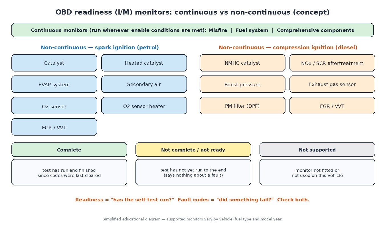
Continuous monitors run whenever their conditions are met, nearly all the time the engine runs:
- Misfire – crankshaft speed variation shows a cylinder that is not contributing.
- Fuel system – fuel trims are watched; if they hit their limits, the mixture cannot be controlled.
- Comprehensive components – sensors and actuators are checked for circuit faults and plausibility.
Non-continuous monitors run once per drive cycle, and only when specific conditions are met. On petrol engines these are catalyst, heated catalyst, EVAP, secondary air, oxygen sensor, oxygen sensor heater and EGR/VVT. On diesels the set is different: NMHC catalyst, NOx/SCR aftertreatment, boost pressure, exhaust gas sensor, PM filter and EGR/VVT. Not every vehicle uses every monitor; unused ones are shown as “not supported”.
We have covered the catalyst monitor separately, so here we focus on how all the monitors fit together.
Drive cycles and enable conditions
A non-continuous monitor waits for its enable conditions. Typical ones include coolant above a minimum temperature, intake air temperature within a range, a stable speed or load for some time, a minimum fuel level for EVAP tests, and no related fault already stored. A thermostat stuck open (P0128) or a faulty sensor can stop several monitors from ever running.
A drive cycle is the sequence of cold start, idle, cruise and deceleration that lets all the monitors run. Procedures are manufacturer-specific, and some monitors only run after others have passed.
Why monitors show “not ready”
Readiness status is reset to “not complete” when:
- fault codes are cleared with a scan tool;
- the battery or ECU supply has been disconnected on many vehicles;
- the ECU has been reprogrammed or replaced, including returning to an original file.
“Not ready” does not mean a fault. It means the test has not finished yet. But nothing is confirmed healthy either, so a vehicle can fail inspection with no codes stored. Rules vary between test programmes, and some accept one or two incomplete monitors. On some Ford vehicles, the manufacturer code P1000 simply reports that monitor testing is not complete.
Pending, confirmed and permanent DTCs
OBD-II and EOBD separate codes into stages:
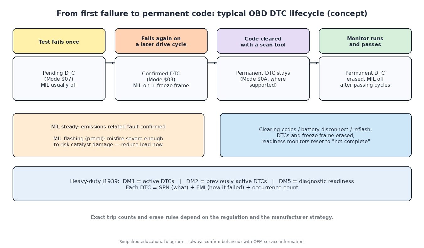
- Pending (Mode $07): a monitor failed once. Many monitors need a second failed drive cycle before the MIL is lit.
- Confirmed (Mode $03): the failure repeated. The MIL comes on and a freeze frame is stored.
- Permanent (Mode $0A): required on newer US-market vehicles. It survives a scan-tool clear and is only erased when the ECU itself sees the monitor pass.
MIL logic: a steady lamp means a confirmed emissions-related fault. On petrol engines a flashing lamp means a misfire severe enough to damage the catalyst, so load should be reduced immediately. After several consecutive passing drive cycles the MIL goes out, and the stored code is later erased after a number of warm-up cycles. The exact counts depend on the regulation and the manufacturer.
Freeze frame (Mode $02)
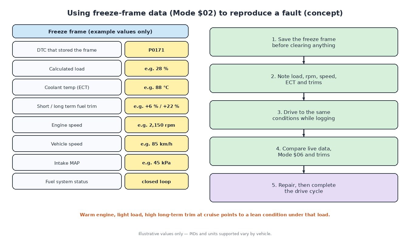
When a code is confirmed, the ECU saves a snapshot of key values at that moment. Common items include:
- the DTC that triggered the frame;
- fuel system status (open or closed loop) and calculated load;
- coolant temperature, short-term and long-term fuel trims;
- engine speed, vehicle speed and intake manifold pressure (MAP);
- often intake air temperature and throttle position.
Usually only one frame is kept, and misfire and fuel system faults get priority. Clearing codes deletes it, so save or photograph it first.
Reproducing the fault: the frame tells you the conditions. A lean code (P0171) stored at warm cruise and light load with a high long-term trim points towards metering or air-leak issues under that load. A lean code stored only at idle suggests a vacuum leak. Recreate the same rpm, load, speed and temperature while logging, then confirm the repair the same way.
Mode $06 test results
Mode $06 shows the actual results of non-continuous tests: each test has a measured value plus minimum and maximum limits. On CAN vehicles they are reported per monitor ID and test ID with standard units. A pass close to its limit is an early warning before any code appears. Interpretation can be manufacturer-specific, so use service data.
Trucks and agricultural machines: SAE J1939
Heavy-duty trucks, tractors and harvesters usually report diagnostics over J1939. The key messages are DM1 (active DTCs), DM2 (previously active DTCs) and DM5 (diagnostic readiness). Each DTC is an SPN (which parameter) plus an FMI (failure mode, e.g. FMI 3 voltage above normal or shorted high, FMI 4 voltage below normal or shorted low) and an occurrence count. SPN 110 FMI 3 is a coolant temperature circuit reading high.
Motorcycles
Euro 5 brought OBD stage II to new motorcycles in the EU, adding monitoring beyond simple circuit faults, and the later Euro 5+ stage added further requirements such as catalyst monitoring. Access and supported modes still vary by manufacturer, so a generic scan tool may not show everything.
Practical diagnostic tips
- Read readiness, pending, confirmed and permanent codes, then save the freeze frame before clearing anything.
- Fix the root cause first; clearing codes only resets the clock.
- Check enable blockers: coolant temperature, fuel level, sensor faults and battery voltage.
- Use Mode $06 to see how close each test is to its limit.
- After any repair or ECU flash, complete the manufacturer drive cycle and recheck readiness.
- Keep catalyst, EGR, DPF and SCR systems intact and working; the monitors exist to protect them and the emissions they control.
Related fault codes (DTCs)
Generic OBD-II/EOBD codes (SAE J2012), one manufacturer-specific example and a J1939 example. Always check service information for the exact vehicle.
| Code | Meaning | Typical causes |
|---|---|---|
| P0300 | Random/Multiple Cylinder Misfire Detected | Ignition, injector or fuel supply faults, vacuum leaks, low compression; set by the continuous misfire monitor |
| P0171 / P0172 | System Too Lean / Too Rich (Bank 1) | Air leaks, MAF/MAP errors, fuel pressure, leaking injectors, exhaust leak before the sensor; set by the fuel system monitor |
| P0128 | Coolant Thermostat (Coolant Temperature Below Thermostat Regulating Temperature) | Thermostat stuck open, ECT sensor fault; a cold-running engine can also stop other monitors from running |
| P0133 | O2 Sensor Circuit Slow Response (Bank 1 Sensor 1) | Aged or contaminated upstream sensor, exhaust leak, wiring |
| P0135 | O2 Sensor Heater Circuit (Bank 1 Sensor 1) | Open heater element, blown fuse, wiring or connector fault |
| P0420 / P0430 | Catalyst System Efficiency Below Threshold (Bank 1 / Bank 2) | Worn catalyst, exhaust leaks, sensor faults, misfire history |
| P0440 / P0442 / P0455 / P0456 | EVAP System Malfunction / Small Leak / Large Leak / Very Small Leak | Loose or faulty filler cap, cracked hoses, purge or vent valve faults, canister damage |
| P0401 | Exhaust Gas Recirculation Flow Insufficient Detected | Carbon-blocked EGR passages or valve, sticking valve, vacuum or position sensor faults |
| P0411 | Secondary Air Injection System Incorrect Flow Detected | Failed air pump, stuck check or switching valve, blocked passages |
| P0299 | Turbocharger/Supercharger “A” Underboost | Boost leaks, sticking wastegate or VGT, actuator or sensor faults |
| P2002 | Diesel Particulate Filter Efficiency Below Threshold (Bank 1) | Damaged or cracked filter, pressure sensor or hose faults |
| P20EE | SCR NOx Catalyst Efficiency Below Threshold (Bank 1) | DEF/AdBlue quality or dosing faults, NOx sensor faults, aged SCR catalyst |
| P0606 | Control Module Processor | Internal ECU fault, supply or ground problems; check power and grounds before condemning the unit |
| U0100 | Lost Communication With ECM/PCM “A” | CAN wiring, connector, ECU power or ground faults, ECU not responding |
| P1000 (Ford, manufacturer-specific) | OBD Monitor Testing Not Complete | Not a fault: shown after codes were cleared or the battery was disconnected, until all monitors have run |
| SPN 110 FMI 3 / FMI 4 (SAE J1939) | Engine Coolant Temperature: voltage above normal or shorted high / below normal or shorted low | Trucks and machines: sensor circuit open or shorted, connector damage |
Closing
Readiness tells you whether the self-tests have run, freeze frame tells you when the fault happened, and Mode $06 tells you how close each test is to failing. Read all three before replacing parts.
Need a custom engineered ECU or TCU file built from your original read? Upload your file at ECUFileMarket.