
Before common rail took over, a whole generation of diesel engines built their injection pressure in a very different way: one small cam-driven pump for each cylinder, switched on and off by a fast solenoid valve. These are unit injector and unit pump systems. They powered Volkswagen Group “Pumpe-Düse” TDI engines in cars and vans, many heavy-duty truck engines, and a long list of agricultural and construction machines. Plenty are still working every day, so technicians and tuners keep meeting them. This guide explains how they work, what the ECU controls, and how to diagnose them.
Two designs, one principle
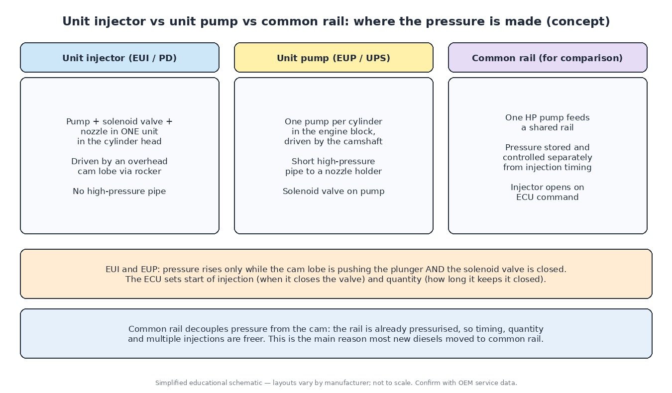
An electronic unit injector (EUI), called Pumpe-Düse (PD) on VW Group engines, combines the pumping plunger, a high-speed solenoid valve and the injection nozzle in one body mounted in the cylinder head. An extra lobe on the overhead camshaft pushes the plunger down through a rocker arm once per cycle. Because pump and nozzle are one part, there is no high-pressure pipe at all.
An electronic unit pump (EUP), also called a unit pump system (UPS) or, on Mercedes-Benz trucks, PLD, puts a separate pump for each cylinder in the engine block, driven by the engine camshaft. A short high-pressure pipe takes fuel to a conventional nozzle holder in the head. This layout suits engines with the camshaft in the block and makes the pumps easier to reach.
In both, the cam only creates the possibility of pressure. While the solenoid valve is open, the plunger just pushes fuel back to the low-pressure side. Pressure only builds once the ECU closes the valve.
How one injection happens
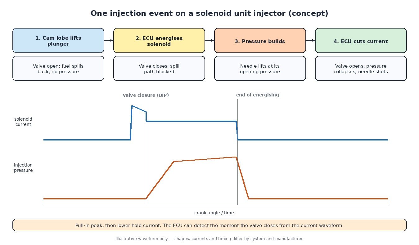
- The cam lobe starts pushing the plunger down. The valve is open, so fuel spills back to the supply gallery.
- The ECU energises the solenoid. The valve closes and the spill path is blocked.
- Pressure rises very quickly until the nozzle needle lifts and fuel is sprayed into the cylinder. Late unit injector designs reach pressures in the region of 2,000 bar.
- The ECU switches the current off, the valve reopens, pressure collapses and the needle snaps shut.
So start of injection is set by when the ECU closes the valve, and quantity mainly by how long it holds it closed, both at a given position on the cam lobe. Some PD injectors also produce a small pilot injection hydraulically, using a spring-loaded piston that briefly interrupts the main injection.
What the ECU needs to know
Because every injection is tied to a cam lobe, the ECU must know exactly where the crankshaft and camshaft are. The crank sensor gives speed and angle; the cam sensor tells it which cylinder is on its injection stroke. Without a cam signal many of these engines will not start at all.
The ECU also watches the solenoid current. A typical drive uses a high pull-in current followed by a lower hold current, and the shape of the waveform shows the instant the valve actually closed. Bosch-type systems call this the beginning of injection period (BIP). Comparing the measured closing point with the commanded one lets the ECU correct timing for each cylinder and flag a unit that responds too slowly.
Other inputs are the usual diesel set: air mass or boost pressure, coolant and fuel temperature, pedal position and vehicle speed. Fuel temperature matters because warm fuel is less dense, so the ECU trims quantity to keep torque consistent. On many truck and machine engines each injector also carries a trim or calibration code that must be entered in the ECU when it is replaced.
Calibration concepts
From a calibration point of view the main maps are driver’s wish and torque limits converted into injected quantity, a quantity-to-duration conversion that depends on engine speed, start-of-injection maps, smoke limits based on air mass or boost, and protection limits. Two points are special to cam-driven systems. Injection pressure rises with engine speed and duration, so low-speed pressure is limited compared with common rail. And longer injections mean longer loading on the cam lobe, rocker and plunger, so mechanical limits matter as much as engine-out temperatures. A sound job always starts from a full original read and respects the manufacturer’s component limits.
Cars, trucks, tractors and bikes
- Cars and vans: VW Group PD TDI engines used unit injectors from the late 1990s until the switch to common rail. The injector wiring runs inside the rocker cover, where heat and oil can damage the loom and connectors.
- Trucks: Unit injectors and unit pumps were common on heavy-duty engines, often with injector trim codes and J1939 diagnostics that report faults per cylinder.
- Agricultural and construction machines: Many engines of the same era used unit pumps because they are robust and easy to service in the block.
- Motorcycles: Road bikes are petrol, so this system does not apply, but the idea of a cam-driven pump controlled by a solenoid is a useful contrast with petrol direct injection.
Diagnosing unit injector and unit pump faults
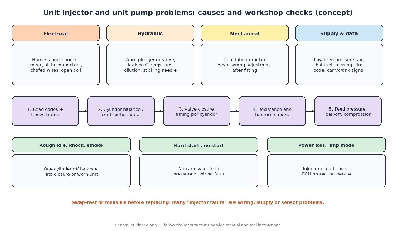
Typical complaints are rough idle, knocking, smoke, hard starting, misfire-like shaking and power loss. A practical routine:
- Read fault codes and freeze-frame data, including manufacturer codes.
- Check cylinder balance or contribution values at warm idle. A cylinder that needs a large correction points to a weak unit, compression loss or a mechanical issue on that cylinder.
- Compare valve closure timing between cylinders where the scan tool shows it.
- Measure solenoid resistance and check the harness, especially connectors under the rocker cover and any sign of oil inside the loom.
- Verify feed pressure, look for air in the fuel, and check for fuel in the oil, which can come from leaking injector seals.
- Inspect cam lobes and rockers when wear is suspected, and follow the exact adjustment procedure after fitting a unit injector.
Related fault codes (DTCs)
Generic OBD-II codes (SAE J2012) plus the J1939 injector parameters used on heavy-duty engines. Manufacturers also use their own codes, so always check the service information for the exact engine.
| Code | Meaning | Typical causes |
|---|---|---|
| P0200 | Injector Circuit/Open | Fault in the common injector supply or control circuit, harness damage, ECU driver fault |
| P0201–P0206 | Injector Circuit/Open – Cylinder 1 to 6 | Open or high-resistance injector coil or wiring for that cylinder, corroded or oil-soaked connector |
| P0261 / P0262 | Cylinder 1 Injector “A” Circuit Low / High | Short to ground or open circuit (low), short to voltage (high); same pattern for other cylinders (P0264/P0265 cylinder 2, P0267/P0268 cylinder 3, P0270/P0271 cylinder 4) |
| P0263 | Cylinder 1 Contribution/Balance | Worn or sticking unit, poor nozzle spray, low compression, cam/rocker wear on that cylinder |
| P0266 / P0269 / P0272 | Cylinder 2 / 3 / 4 Contribution/Balance | As above for the cylinder concerned |
| P0216 | Injector/Injection Timing Control Circuit | Timing control circuit fault, valve closure outside expected window, sync problems |
| P0251 | Injection Pump Fuel Metering Control “A” (Cam/Rotor/Injector) | Metering solenoid or valve fault, wiring, mechanical wear in the pumping element |
| P0180 | Fuel Temperature Sensor “A” Circuit | Failed fuel temperature sensor or wiring; affects quantity correction |
| P0182 / P0183 | Fuel Temperature Sensor “A” Circuit Low / High | Short to ground (low) or open/short to voltage (high) |
| P0335 | Crankshaft Position Sensor “A” Circuit | No or poor crank signal: sensor, air gap, wiring, damaged reluctor |
| P0340 | Camshaft Position Sensor “A” Circuit (Bank 1 or Single Sensor) | No cam signal: the ECU cannot assign injections to cylinders |
| P0016 | Crankshaft Position – Camshaft Position Correlation (Bank 1 Sensor A) | Timing belt/chain or gear misalignment, wrong cam sensor reluctor, sensor fault |
| P062D | Fuel Injector Driver Circuit Performance Bank 1 | ECU injector output stage fault, shorted injector loading the driver, harness short |
| P0611 | Fuel Injector Control Module Performance | Fault in a separate injector driver module or its supply/communication |
| SPN 651–656 (SAE J1939) | Engine Injector Cylinder #1 to #6 (the FMI number gives the failure type) | Heavy-duty trucks and machines: injector circuit, mechanical or response fault for that cylinder |
Closing
A unit injector or unit pump is a cam-driven pump that only makes pressure while the ECU keeps its valve closed. Get the cam and crank signals, wiring and supply right before blaming the injector itself.
Need a custom engineered ECU or TCU file built from your original read? Upload your file at ECUFileMarket.