
Almost every control unit in a modern vehicle wants to know how fast the vehicle is moving. The ABS and stability system needs each wheel’s speed to stop it locking or spinning, the transmission control unit uses road speed to choose gears, and the engine ECU uses it for cruise control, speed limiting and several idle and overrun strategies. All of this starts with a handful of simple sensors. This guide explains how wheel speed and vehicle speed sensors work, how the signal travels around the vehicle, and how to diagnose them on cars, trucks, agricultural machines and motorcycles.
What the sensor actually measures
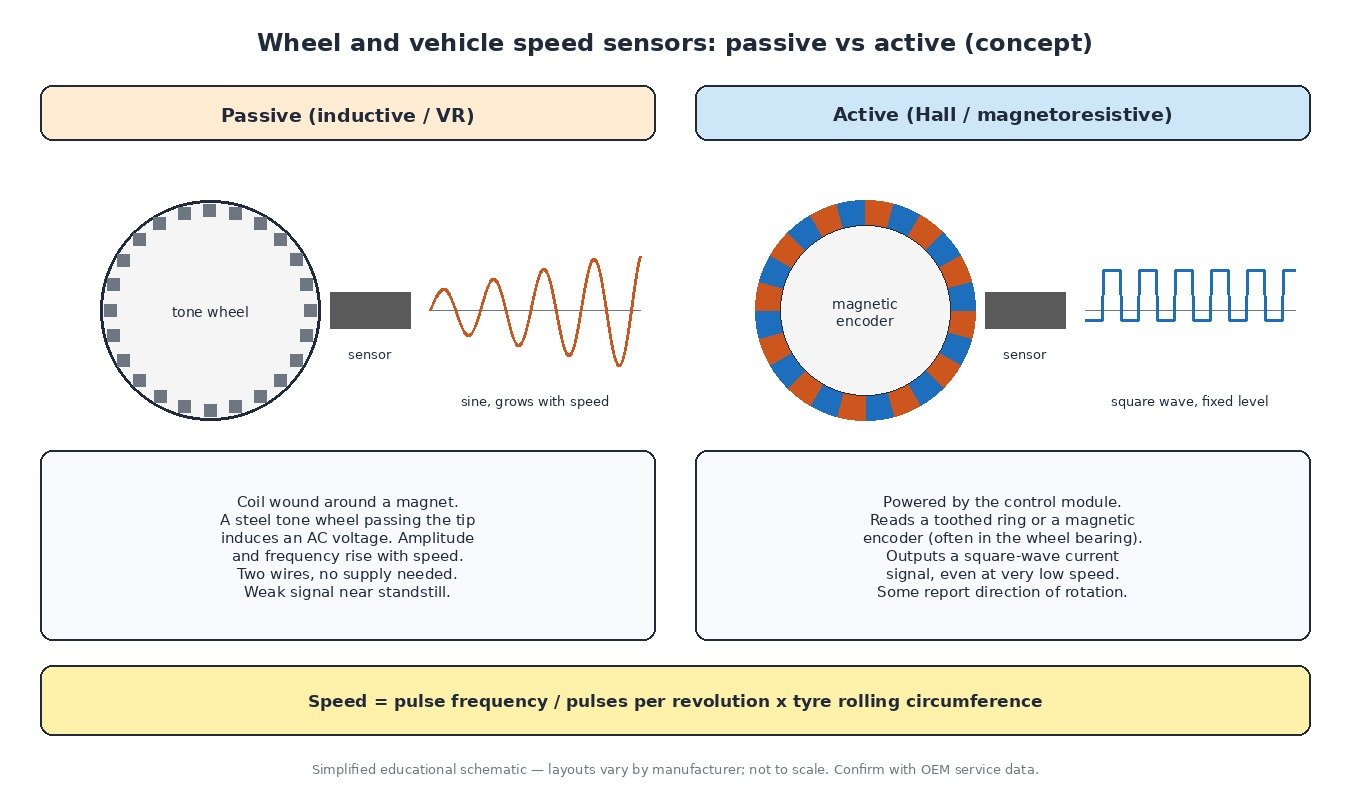
A speed sensor does not measure speed directly. It counts teeth or magnetic poles passing its tip on a rotating part: a tone ring on the hub or driveshaft, a magnetic encoder built into the wheel bearing seal, or a target wheel inside the gearbox. The control unit counts the pulses over time. Knowing how many pulses there are per revolution and the rolling circumference of the tyre, it converts pulse frequency into wheel speed and then road speed.
That conversion explains a common complaint: when tyre size changes, or one tyre is badly worn, the calculated speed changes too, even though the sensor itself is perfect.
Passive (inductive) sensors
Older systems and many gearbox sensors use passive, variable-reluctance sensors. Inside is a permanent magnet with a coil wound around it. As each steel tooth passes, the magnetic field through the coil changes and a small AC voltage is induced. Both the frequency and the amplitude of that voltage rise with speed.
- They need no power supply and usually have two wires.
- At very low speed the signal becomes too weak to read reliably, so the system has a minimum detectable speed.
- The air gap between sensor and ring matters: too large a gap, or a rusty ring, gives a weak or distorted signal.
Active (Hall and magnetoresistive) sensors
Most current ABS systems use active sensors. The control module supplies them with power, and an internal Hall or magnetoresistive element detects the passing teeth or magnetic poles. Electronics inside the sensor turn this into a clean square-wave signal, often as a current that switches between two levels.
- They work down to almost standstill, which helps hill-hold, low-speed stability control and parking functions.
- Some versions also report direction of rotation and can send status information.
- Because the signal level does not depend on speed, faults show up as missing pulses or a lost supply rather than a weak signal.
Magnetic encoder rings are easy to damage. A bearing pressed in the wrong way round, a magnet placed against the seal, or metal swarf stuck to it can all corrupt the signal.
How the speed signal is shared
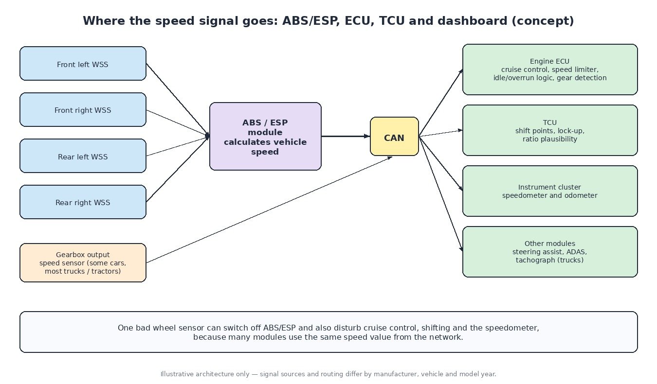
On most modern cars the four wheel speed sensors are wired to the ABS/ESP module. That module calculates individual wheel speeds and a vehicle reference speed, and puts them on the CAN network. The engine ECU, transmission control unit, instrument cluster, steering assist and driver-assistance systems then read that value from the network instead of having their own sensors.
Some vehicles also have speed sensors inside the gearbox: an input or turbine speed sensor and an output speed sensor. The TCU compares them to calculate gear ratio, slip and torque converter lock-up. Many trucks and tractors take road speed from the gearbox output shaft, and on trucks that signal is also used by the tachograph.
What the ECU and TCU do with road speed
- Cruise control and speed limiters: the ECU compares actual speed with the target and adjusts the torque request.
- Gear detection: engine speed divided by road speed tells the ECU which gear is engaged on manual gearboxes, used for per-gear torque limits and drivability maps.
- Shift strategy: the TCU uses output speed and load to choose shift points and lock-up.
- Plausibility checks: if road speed is zero while the engine is under load in gear, the ECU knows something is wrong and stores a code.
When the speed signal is lost, ECUs usually disable cruise control and may use substitute values. TCUs often move into a limp-home mode with a fixed gear.
Differences between vehicle types
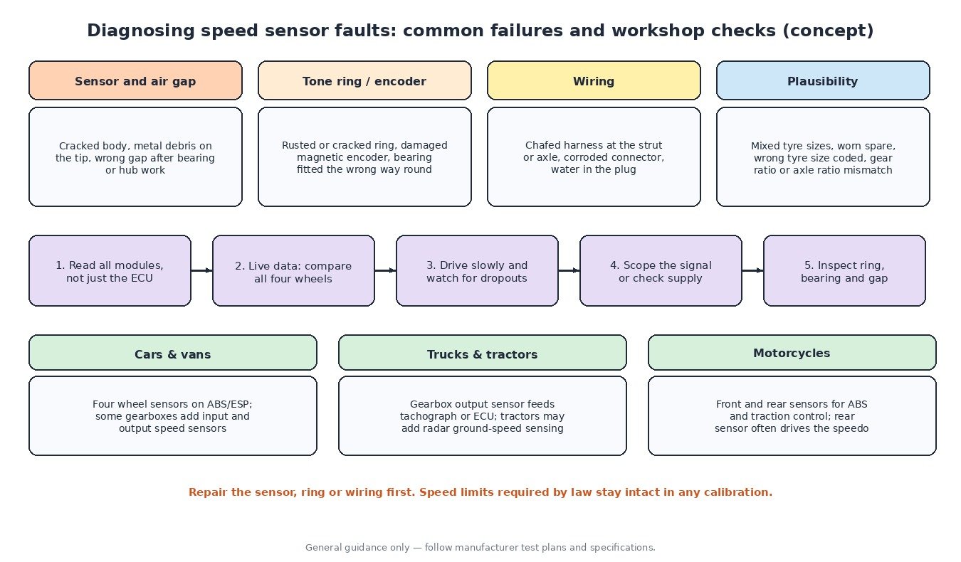
Cars and vans use four wheel sensors for ABS/ESP, with gearbox speed sensors on automatic and dual-clutch gearboxes. Trucks have wheel sensors for the braking system plus a gearbox output sensor; the speed limiter required by law uses this road speed. Agricultural tractors often combine wheel or gearbox speed with a radar ground-speed sensor, because wheel slip in the field makes wheel speed unreliable for work rate and implement control. Motorcycles with ABS have a sensor on each wheel; comparing front and rear speed is also the basis of traction control.
Diagnosing speed sensor faults
- Read every module, not only the engine ECU. A wheel speed fault is usually stored in the ABS module, while the ECU and TCU only show follow-up codes.
- Compare all wheel speeds in live data while driving slowly in a straight line. A sensor that drops out or reads differently from the others stands out quickly.
- For passive sensors, check the coil resistance against specification and look at the AC signal with an oscilloscope while turning the wheel.
- For active sensors, confirm supply voltage at the connector and watch the square wave with a scope or the module’s live data.
- Inspect the tone ring or encoder, the bearing, the sensor tip and the air gap, especially after hub or bearing work.
- Check tyre sizes and any coded tyre circumference before blaming a sensor for an implausible speed.
What it means for ECU calibration
Speed-related functions such as per-gear torque limits, vehicle speed limiters and cruise control live in the calibration. Any tuning work should start with a healthy speed signal, because a dropout distorts datalogs and can trigger limp modes that look like a calibration problem. Legally required speed limitation on trucks and buses, and speed limits linked to type approval, stay intact.
Related fault codes (DTCs)
Generic OBD-II codes (SAE J2012). Wheel speed sensor codes stored in the ABS module are usually manufacturer-specific, so read them with the correct OEM description for the vehicle.
| Code | Meaning | Typical causes |
|---|---|---|
| P0500 | Vehicle Speed Sensor “A” | No or implausible speed signal: failed sensor, wiring or connector fault, missing speed message from the ABS module |
| P0501 | Vehicle Speed Sensor “A” Range/Performance | Speed does not match engine speed and gear, wrong tyre size, damaged tone ring, intermittent wiring |
| P0502 | Vehicle Speed Sensor “A” Circuit Low Input | Open or shorted signal circuit, sensor failure, poor ground |
| P0503 | Vehicle Speed Sensor “A” Intermittent/Erratic/High | Loose connector, chafed wiring, electrical interference, metal debris on the sensor tip |
| P0574 | Cruise Control System – Vehicle Speed Too High | Vehicle speed above the cruise control limit, or an incorrect speed signal |
| P0715 | Input/Turbine Speed Sensor “A” Circuit | Gearbox input speed sensor or wiring fault, connector corrosion, low transmission fluid on some designs |
| P0716 | Input/Turbine Speed Sensor “A” Circuit Range/Performance | Erratic sensor signal, internal gearbox slip, wiring interference |
| P0717 | Input/Turbine Speed Sensor “A” Circuit No Signal | Open circuit, failed sensor, damaged reluctor or target |
| P0720 | Output Speed Sensor Circuit | Gearbox output speed sensor or wiring fault, connector damage |
| P0721 | Output Speed Sensor Circuit Range/Performance | Signal does not match wheel speeds, debris on the sensor, damaged target wheel |
| P0722 | Output Speed Sensor Circuit No Signal | Open circuit, failed sensor, unplugged connector |
| P0723 | Output Speed Sensor Circuit Intermittent | Loose terminal, chafed wiring, vibration-related break |
| U0121 | Lost Communication With Anti-Lock Brake System (ABS) Control Module | ABS module power or ground fault, CAN wiring fault, failed module |
| U0415 | Invalid Data Received From Anti-Lock Brake System (ABS) Control Module | ABS module reporting an invalid speed value, often after a wheel speed sensor fault stored in the ABS module |
Closing
Wheel and vehicle speed sensors are simple parts, but many modules depend on them. Reading every module and comparing all speed values side by side usually points straight to the faulty wheel, ring or wire.
Need a custom engineered ECU or TCU file built from your original read? Upload your file at ECUFileMarket.