
Every engine control unit carries a set of limits that decide how much torque, engine speed or road speed the vehicle is allowed at any moment. This article explains how ECU limiters work from an engineering point of view: what each limiter protects, how it removes torque and how limiters fit into the torque model on cars, trucks, agricultural machines and motorcycles.
Limiters are part of the torque model
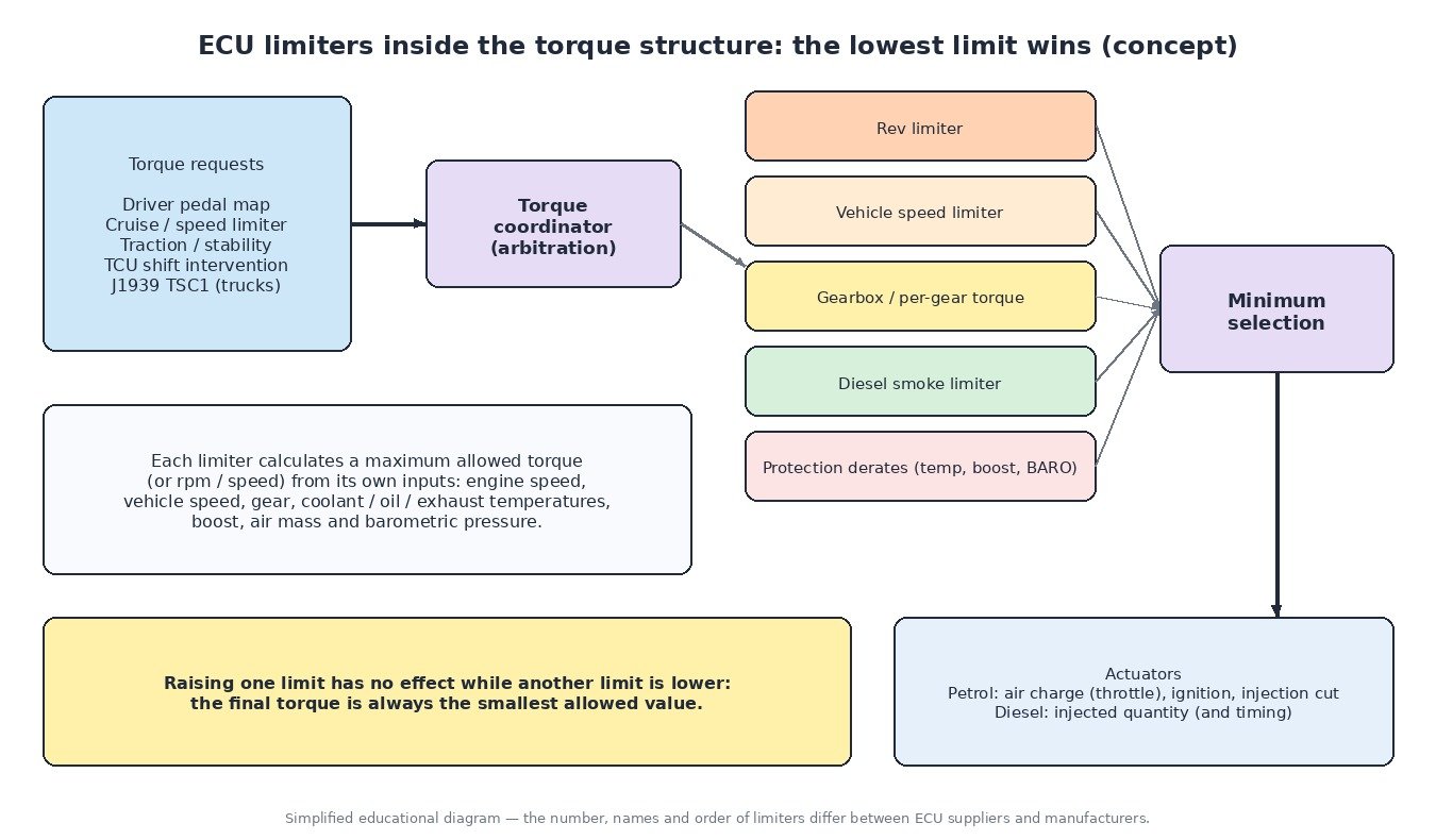
In a modern torque-based ECU, requests from the pedal, cruise control, traction control or the gearbox are arbitrated by a torque coordinator. Each limiter calculates a maximum allowed value from its own inputs, and the ECU applies the lowest one. That is why one limiter can hide another.
Rev limiter
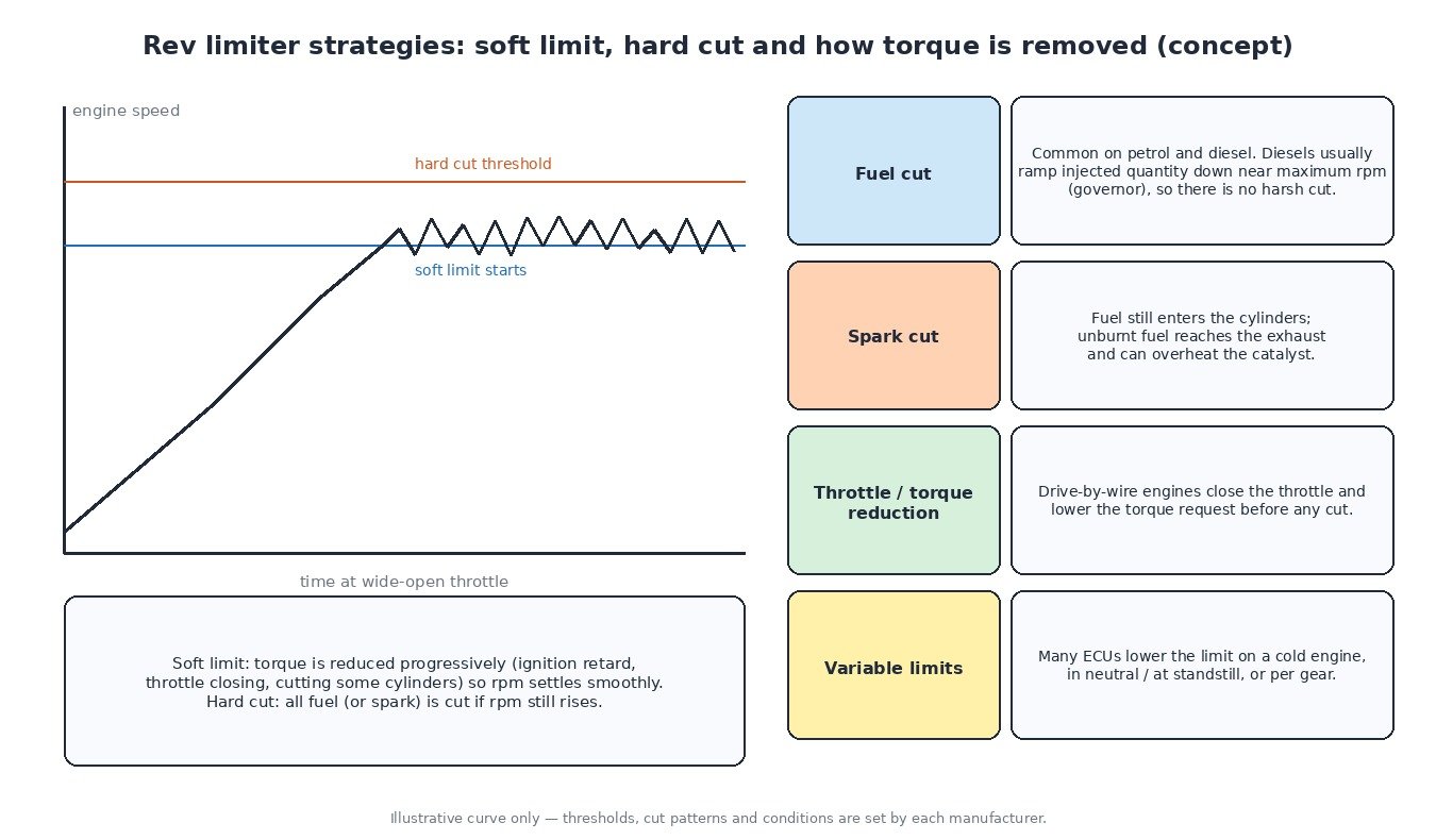
The rev limiter protects the engine from overspeed. Many petrol ECUs use a soft limit first, removing torque progressively through ignition retard, throttle closing or cutting individual cylinders, followed by a hard cut of all fuel if engine speed still rises. Fuel cut is the most common method. Spark cut leaves fuel entering the cylinders, which reaches the exhaust unburnt and can overheat the catalyst. Diesel engines normally use a governor that ramps injected quantity down near maximum speed instead of a harsh cut.
The limit is often not fixed. Many ECUs lower it while the engine is cold, based on coolant or oil temperature, apply a lower limit in neutral or at standstill, or use a different limit per gear. Launch control is a standstill limiter that holds engine speed at a calibrated value for a consistent start.
Vehicle speed limiter
The road speed limiter compares the vehicle speed signal with a maximum value and reduces the torque request as speed approaches it. The speed signal comes from a gearbox output sensor or, on most current vehicles, from the wheel speed sensors via the ABS module over CAN. Driver-set adjustable speed limiters (ASL) and cruise control use the same signal and usually switch off when the brake or clutch switch is pressed, which is why brake switch faults often disable them.
Some speed limiters are legal requirements. Directive 92/6/EEC requires speed limitation devices on buses and heavy goods vehicles in the EU, and Regulation (EU) 2019/2144 requires Intelligent Speed Assistance (ISA) on new vehicles, a system that uses speed-limit information to warn the driver. These functions must stay in place and working; removing them is not a service ECUFileMarket offers.
Torque limiters
Gearboxes, clutches and driveshafts have a rated torque capacity, so the ECU applies maximum torque limits, often per gear, with lower values in first gear or reverse. Automatic and dual-clutch transmissions also ask the engine for brief torque reductions during shifts. If communication with the TCU is lost, many ECUs fall back to a conservative torque limit to protect the transmission.
Diesel smoke limiter
A diesel can inject more fuel than the available air can burn cleanly. The smoke limiter caps injected quantity based on measured air mass or boost pressure and intake temperature, usually expressed as a minimum lambda. It is closely linked to emissions and particulate filter loading.
Protection limiters and derates
- Temperature: coolant, oil, intake air, transmission fluid and exhaust gas temperature (measured or modelled) can each reduce torque when too high.
- Boost: a maximum boost limit and overboost detection protect the turbo and engine.
- Altitude: with lower barometric pressure the turbo must spin faster to make the same boost, so the ECU derates torque or boost using the BARO sensor.
Vehicle-type notes
Cars share limits between the engine ECU, TCU and stability control. Trucks and buses use a road speed governor in the engine ECU, and other modules such as the transmission, retarder and ABS request torque or speed limits over the SAE J1939 network using the Torque/Speed Control (TSC1) message. Agricultural machines rely on engine speed governors that hold rpm under changing load, often with PTO modes for the standard 540 and 1000 rpm PTO shaft speeds, and they derate on high temperatures or low reductant level. Motorcycles often have rev limits per gear, ride modes that change throttle response and maximum torque, and traction control that cuts torque through ignition, fuel or the electronic throttle.
Calibration concepts
Because the ECU always takes the lowest limit, raising one value often changes nothing until the next limiter in the chain is identified. Every limit also reflects a component capability, such as clutch and gearbox torque rating, turbo speed or cooling capacity, so any change must stay within what the hardware can take and be verified with a datalog. Emission-related limits and legally required limiters, such as speed limitation devices on heavy vehicles, must remain intact. DPF, EGR and AdBlue/SCR are systems the calibration has to work with, not remove.
Related fault codes (DTCs)
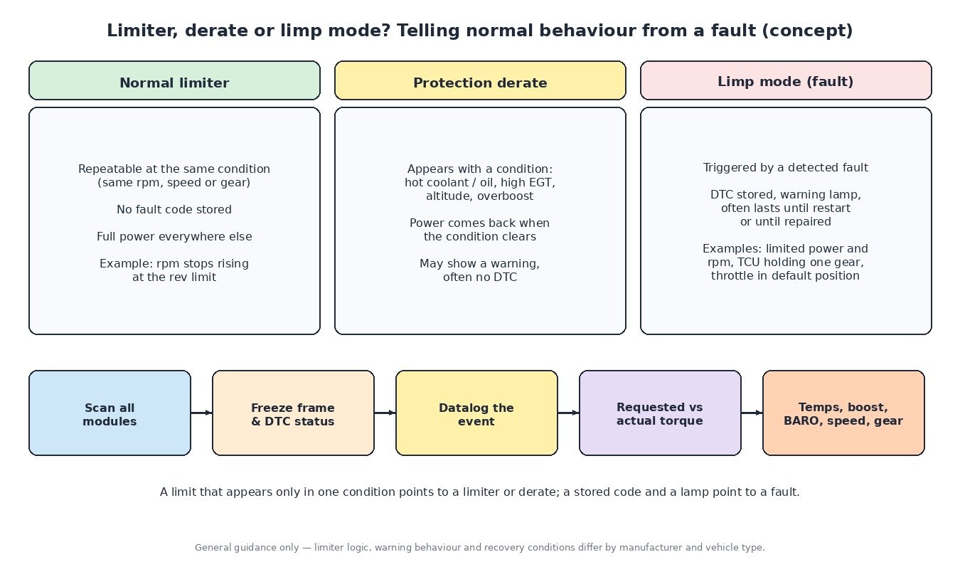
Generic OBD-II codes (SAE J2012). Manufacturer wording varies, and many limiter events store no code at all because they are normal operation.
| Code | Meaning | Typical causes |
|---|---|---|
| P0219 | Engine Overspeed Condition | Missed downshift, engine driven over limit downhill, speed signal fault |
| P0500 | Vehicle Speed Sensor “A” | Failed speed or wheel speed sensor, wiring, missing CAN speed signal |
| P0501 | Vehicle Speed Sensor “A” Range/Performance | Implausible signal, wrong tyre size coding, damaged tone ring |
| P0502 | Vehicle Speed Sensor “A” Circuit Low | Short to ground, open circuit, failed sensor |
| P0503 | Vehicle Speed Sensor “A” Intermittent/Erratic/High | Loose connector, chafed wiring, debris on the sensor |
| P0504 | Brake Switch “A”/”B” Correlation | Misadjusted or failed brake switch, fuse or wiring fault |
| P0571 | Brake Switch “A” Circuit | Brake switch or circuit fault; cruise and speed limiter often disabled |
| P0217 | Engine Coolant Over Temperature Condition | Low coolant, thermostat, pump or fan failure, blocked radiator |
| P0218 | Transmission Fluid Over Temperature Condition | Heavy load or towing, low or old fluid, blocked cooler, slipping clutches |
| P0524 | Engine Oil Pressure Too Low | Low oil level, worn pump or bearings, faulty sensor |
| P0234 | Turbocharger/Supercharger “A” Overboost Condition | Sticking wastegate or VGT, actuator or sensor fault |
| P0299 | Turbocharger/Supercharger “A” Underboost Condition | Boost leak, split hose, actuator fault, worn turbo |
| P2227 | Barometric Pressure Sensor “A” Circuit Range/Performance | Faulty BARO sensor, plausibility error against MAP sensor |
| P2135 | Throttle/Pedal Position Sensor/Switch “A”/”B” Voltage Correlation | Worn throttle sensor track, wiring or connector fault |
| P2138 | Throttle/Pedal Position Sensor/Switch “D”/”E” Voltage Correlation | Worn pedal sensor, wiring, supply or ground fault |
| P0606 | Control Module Processor | Internal ECU fault, supply problems, corrupted software |
| P0700 | Transmission Control System (MIL Request) | TCU has stored a fault; read the TCU for details |
| U0101 | Lost Communication With TCM | CAN wiring fault, TCU power or ground loss, failed TCU |
Closing
Limiters are the ECU’s way of keeping torque, speed and temperature inside safe and legal boundaries. Knowing how they interact makes diagnosis and calibration more predictable.
Need a custom engineered ECU or TCU file built from your original read? Upload your file at ECUFileMarket.