
Petrol evaporates easily. Every time a tank warms up in the sun, is shaken on the road or is filled at the pump, fuel vapour forms above the liquid. The evaporative emission control system, usually called EVAP, captures that vapour, stores it and lets the engine burn it later instead of releasing it to the air. This guide explains the main components, how the ECU controls purge and checks the system for leaks, and what EVAP activity means for anyone reading fuel trims on cars, vans, light trucks, utility machines and motorcycles.
The main components
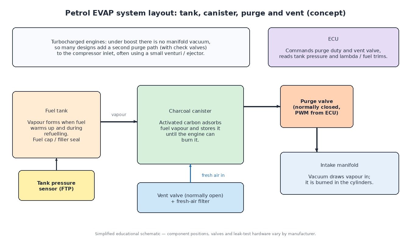
- Charcoal canister: a container filled with activated carbon. Vapour from the tank flows into it and the carbon adsorbs the hydrocarbons, so only air leaves through the vent side.
- Purge valve (purge solenoid): a normally closed valve between the canister and the intake. When the ECU opens it, manifold vacuum pulls fresh air through the canister, strips the stored vapour off the carbon and carries it into the cylinders.
- Canister vent valve: on systems with leak detection, a normally open valve on the canister’s fresh-air side, usually with a dust filter. The ECU closes it to seal the system for a leak test.
- Fuel tank pressure sensor: measures small pressure or vacuum differences in the tank or vapour lines relative to atmosphere. It is the main input for most leak tests.
- Fuel cap or capless filler: part of the sealed system. A worn seal or a cap left loose is one of the most common reasons for an EVAP leak code.
How the ECU controls purge
The purge valve is normally driven with a pulse-width-modulated (PWM) signal. A higher duty cycle opens the valve for a larger share of each cycle, and the actual flow depends on that duty and on the vacuum available across the valve. Purge is usually only enabled once the engine is warm and running in closed-loop lambda control, and the ECU tends to ramp it up gradually rather than open the valve fully at once.
The vapour from the canister is extra fuel the injectors did not deliver, and its concentration is unknown at first. A full canister after a hot day can add a lot of fuel; an empty canister adds mostly air. The ECU therefore watches the lambda signal as purge opens. If the mixture goes rich, it reduces injected fuel and builds an estimate of the vapour load. Many ECUs keep this purge correction separate from long-term mixture adaptation, and some learn mixture adaptation only in windows when purge is closed, so canister vapour is not mistaken for an injector or air-metering error.
Turbocharged engines have a complication: under boost there is no vacuum in the intake manifold. Many designs add a second purge path to the compressor inlet, often with a small venturi or ejector and check valves, so vapour can still be drawn off under load.
How the ECU checks for leaks
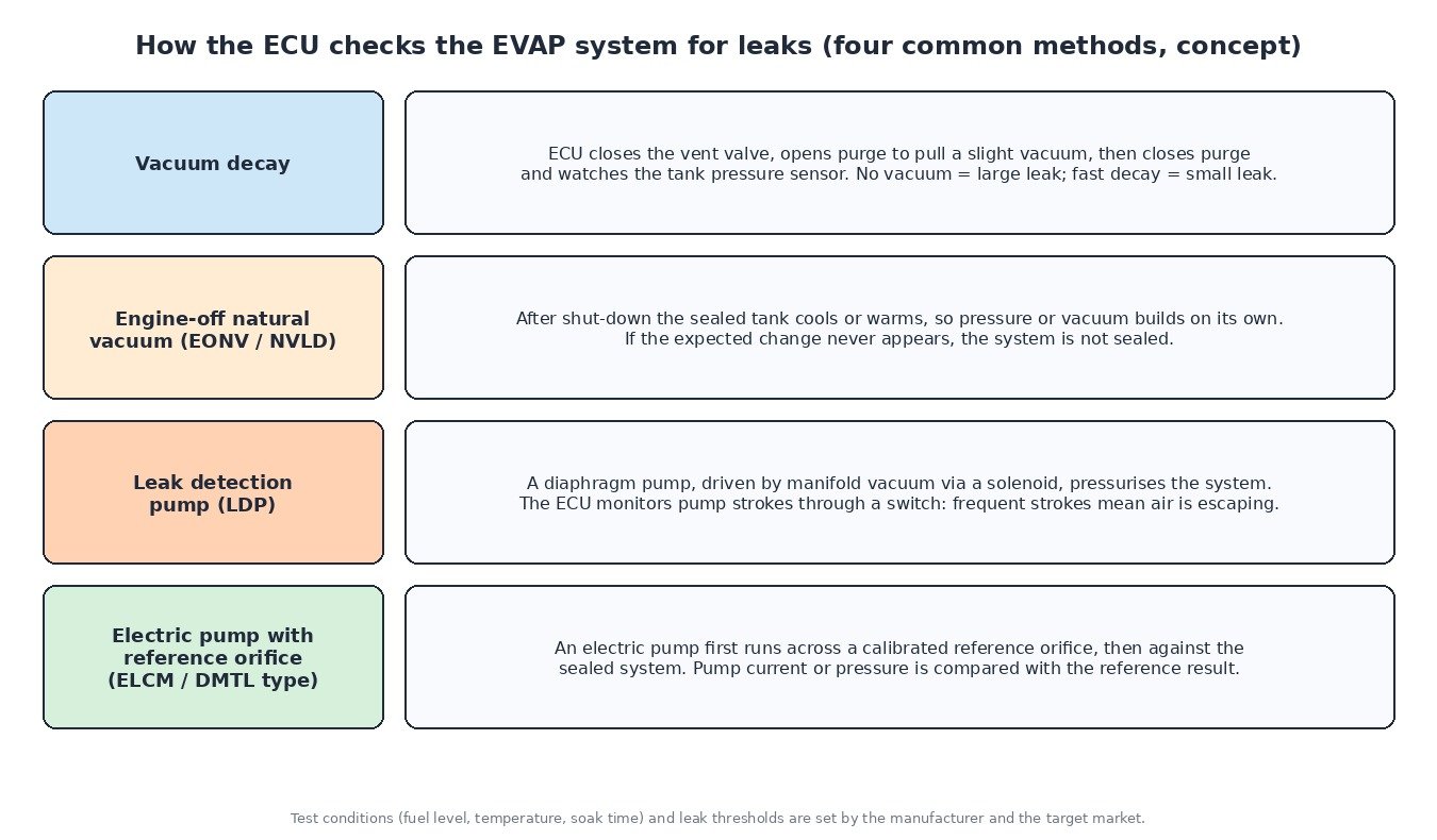
Where regulations require leak monitoring, which is the case for most light vehicles sold in North America, manufacturers use one of several strategies:
- Vacuum decay: with the engine running, the ECU closes the vent valve and opens purge to pull a slight vacuum, then closes purge and watches the tank pressure sensor. If vacuum cannot be reached, a large leak is suspected; if it decays too quickly, a small one.
- Engine-off natural vacuum: after shut-down the fuel in a sealed tank cools or warms, so pressure or vacuum develops on its own. Systems such as EONV or NVLD look for that change; if it never appears, the system is not sealed.
- Leak detection pump (LDP): a diaphragm pump, operated by manifold vacuum through a solenoid, pressurises the system slightly. The ECU monitors the pump strokes through a switch; frequent strokes mean air is escaping.
- Electric pump with reference orifice: modules often called ELCM or DMTL run an electric pump first across a calibrated reference orifice and then against the sealed system, and compare pump current or pressure with the reference result.
Leak tests only run under specific conditions such as fuel level, temperature and soak time, so a repair may take several drive cycles to be confirmed. Many European-market versions of the same model monitor the purge valve and its circuit but carry no tank leak test hardware.
Diagnosing EVAP faults
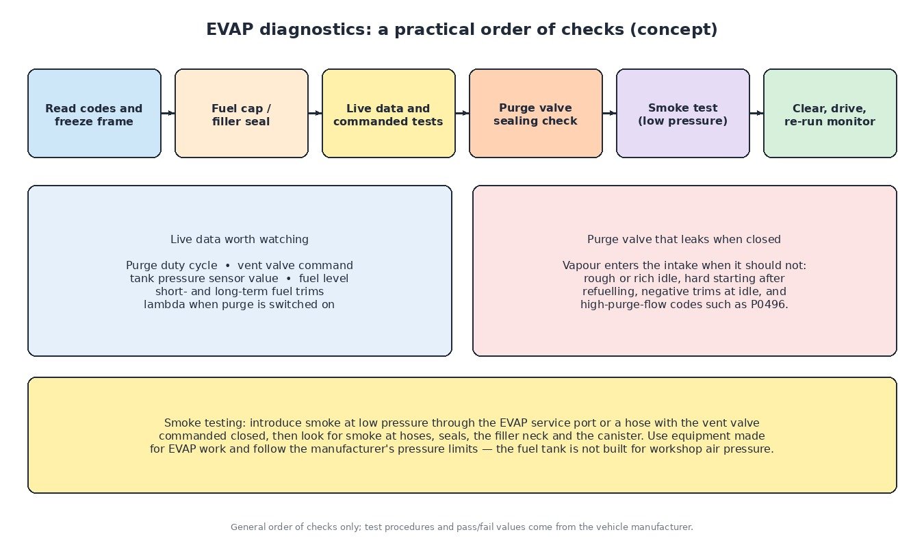
Start with the code and freeze frame, then the simplest part: the fuel cap and filler neck seal. In live data, compare commanded purge duty with what the fuel trims and the tank pressure sensor do, and use the scan tool’s output tests to operate the purge and vent valves. A purge valve that leaks when it should be closed lets vapour into the intake at idle and after refuelling, causing rich running, hard starting and negative trims. It can be checked with a hand vacuum pump: an unpowered valve should hold vacuum. Leaks in hoses, seals and the canister are best found with a low-pressure smoke test through the service port or a suitable hose, using equipment made for EVAP work.
Vehicle-type notes
Cars and vans use the layouts above, with the canister often near the tank or in the engine bay. Petrol and LPG bi-fuel light trucks still have a petrol tank with its own EVAP system, so it must stay connected and working; when reading trims in either fuel mode, check whether purge is active. Petrol agricultural and utility machines such as UTVs, ATVs and small engines may use a canister and low-permeation fuel lines where emission rules require it, sometimes with a simple passive purge rather than an ECU-controlled valve. Motorcycles sold as California models, and many recent European models built to Euro 5 rules, carry a canister, usually with a purge valve feeding the throttle bodies.
Tuning and datalogging notes
EVAP should always stay intact and working as the manufacturer designed it. It is part of the emission system and the ECU’s own diagnostics rely on it. For calibration work, the important point is that purge directly affects mixture readings. When logging, record purge duty alongside lambda and fuel trims: a negative short-term trim at part load may simply be canister vapour, not a rich fuel map. Compare trims in sections where purge is closed before drawing conclusions, and let adaptations settle after any change.
Related fault codes (DTCs)
Generic OBD-II codes (SAE J2012). Manufacturer wording and the exact code set vary, and not every vehicle has leak detection hardware.
| Code | Meaning | Typical causes |
|---|---|---|
| P0440 | Evaporative Emission System Malfunction | General EVAP fault: leak, purge or vent valve problem, tank pressure sensor fault |
| P0441 | Evaporative Emission System Incorrect Purge Flow | Purge valve stuck or blocked, cracked or disconnected purge hose, saturated canister |
| P0442 | Evaporative Emission System Leak Detected (Small Leak) | Worn fuel cap or filler seal, cracked hose, leaking canister or valve seal |
| P0443 | Evaporative Emission System Purge Control Valve “A” Circuit | Purge valve wiring, connector or coil fault |
| P0444 | Evaporative Emission System Purge Control Valve “A” Circuit Open | Open circuit in wiring or valve coil, unplugged connector |
| P0445 | Evaporative Emission System Purge Control Valve “A” Circuit Shorted | Shorted valve coil or wiring |
| P0446 | Evaporative Emission System Vent Control Circuit | Vent valve stuck or not responding, blocked vent filter, wiring fault |
| P0447 | Evaporative Emission System Vent Control Circuit Open | Open wiring or vent valve coil, unplugged connector |
| P0448 | Evaporative Emission System Vent Control Circuit Shorted | Shorted vent valve coil or wiring |
| P0449 | Evaporative Emission System Vent Valve/Solenoid Circuit | Vent solenoid or wiring fault, corrosion at the connector |
| P0450 | Evaporative Emission System Pressure Sensor/Switch “A” Circuit | Tank pressure sensor or wiring fault |
| P0451 | Evaporative Emission System Pressure Sensor/Switch “A” Circuit Range/Performance | Implausible sensor reading, sensor drift, blocked sensor port |
| P0452 | Evaporative Emission System Pressure Sensor/Switch “A” Circuit Low | Signal shorted to ground or open 5 V reference, failed sensor |
| P0453 | Evaporative Emission System Pressure Sensor/Switch “A” Circuit High | Signal shorted to voltage or open ground, failed sensor |
| P0454 | Evaporative Emission System Pressure Sensor/Switch “A” Circuit Intermittent | Loose or corroded connector, chafed wiring |
| P0455 | Evaporative Emission System Leak Detected (Large Leak) | Fuel cap missing, disconnected hose, vent valve stuck open, purge valve stuck closed during the test |
| P0456 | Evaporative Emission System Leak Detected (Very Small Leak) | Ageing cap seal, small hose cracks, leaking filler neck or valve seal |
| P0457 | Evaporative Emission System Leak Detected (Fuel Cap Loose/Off) | Cap not tightened after refuelling, damaged or wrong cap |
| P0496 | Evaporative Emission System High Purge Flow | Purge valve leaking or stuck open, vapour flow when no purge is commanded |
| P0497 | Evaporative Emission System Low Purge Flow | Restricted purge line or valve, blocked canister, purge path check valve fault |
| P2400 | Evaporative Emission System Leak Detection Pump Control Circuit/Open | Open wiring or pump/solenoid coil, unplugged connector |
| P2401 | Evaporative Emission System Leak Detection Pump Control Circuit Low | Control circuit shorted to ground, failed pump or solenoid |
| P2402 | Evaporative Emission System Leak Detection Pump Control Circuit High | Control circuit shorted to voltage, failed pump or solenoid |
Closing
The EVAP system is simple in concept: store vapour, burn it when the engine can, and prove the system is sealed. Knowing how purge and leak tests work makes both diagnostics and datalog interpretation more reliable.
Need a custom engineered ECU or TCU file built from your original read? Upload your file at ECUFileMarket.