
On a loaded truck coming down a long mountain pass, the service brakes alone would overheat long before the bottom. That is why heavy diesels, many fast road-going tractors and plenty of light commercial vehicles use engine braking systems that turn the engine into an air compressor or an air pump that resists motion. This article explains how exhaust brakes, compression-release brakes and VGT braking work, how the ECU decides when they may operate, what typically goes wrong, and why the braking logic matters when an ECU file is engineered.
Why an engine can brake at all
When the driver lifts off, a modern diesel ECU cuts injection to zero. With no combustion, the pistons still have to move air through the engine, and friction plus pumping work slow the vehicle a little. A petrol engine brakes more strongly on overrun than a diesel because the closed throttle creates high intake vacuum; diesels usually run unthrottled, so their natural engine braking is weak. Dedicated engine brakes add a large, controllable source of resistance on top of that.
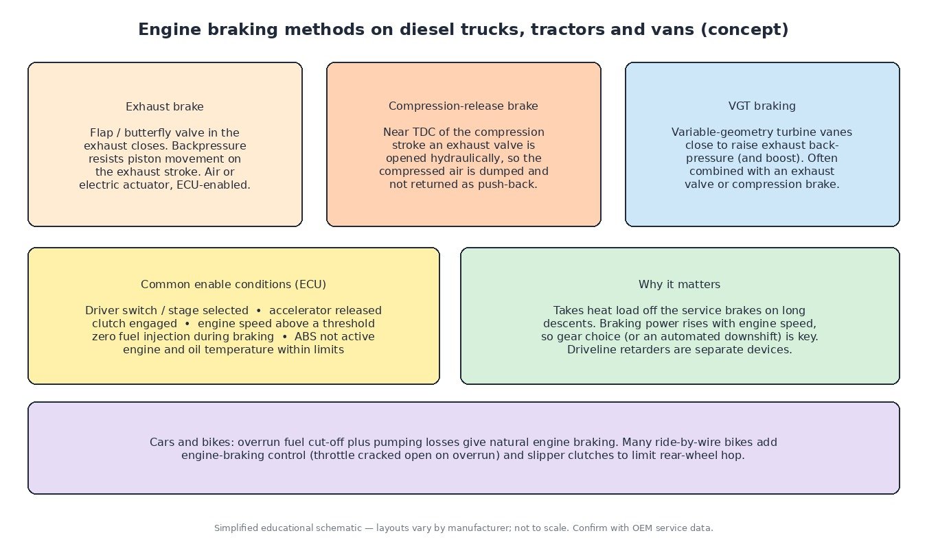
Exhaust brake
An exhaust brake is a flap or butterfly valve placed in the exhaust, usually after the turbine. When it closes, exhaust back-pressure rises sharply and the pistons must push against it on every exhaust stroke. On heavy trucks the valve is normally driven by a compressed-air cylinder through a solenoid valve; lighter vehicles may use vacuum or an electric actuator. Some designs modulate the valve against an exhaust pressure sensor so back-pressure stays inside a safe window for the valves and turbocharger.
Compression-release brake
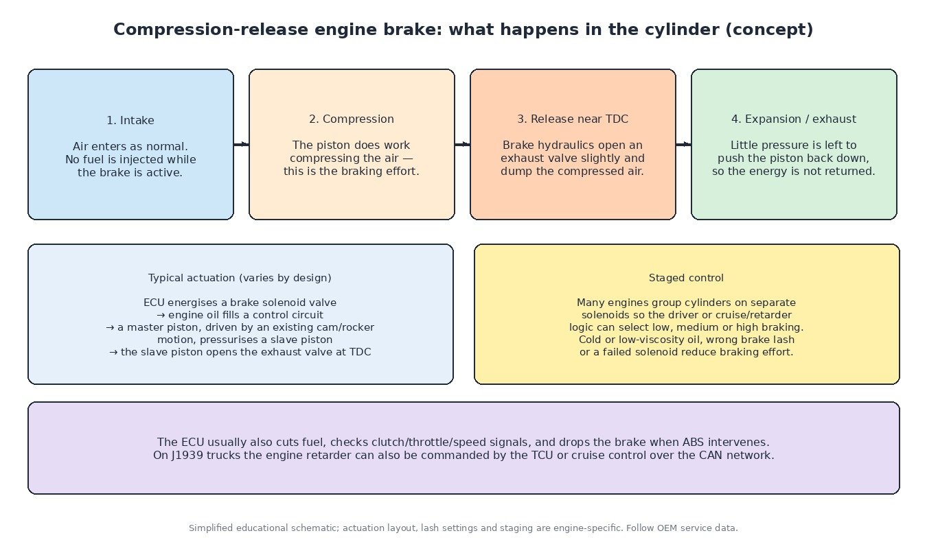
A compression-release brake works differently. The piston compresses air on the compression stroke as usual, which absorbs energy. Then, near top dead centre, the brake mechanism opens an exhaust valve and dumps that compressed air into the exhaust. Because the pressure is gone, it cannot push the piston back down on the expansion stroke, so the energy spent compressing it is not returned to the crankshaft.
Actuation is usually hydraulic, using engine oil. The ECU energises a brake solenoid; oil fills a control circuit; a master piston driven by an existing cam or rocker motion pressurises a slave piston; and the slave piston opens the exhaust valve at the right moment. Cylinders are commonly grouped on separate solenoids, which gives several braking stages. Some engines use a related “bleeder” approach that holds an exhaust valve slightly open during braking instead of releasing at a precise point.
VGT braking
On engines with a variable-geometry turbocharger, the ECU can close the turbine vanes during braking. That raises exhaust back-pressure and, at the same time, boost, so more air is compressed and pushed through the engine. Many modern diesel pickups and vans use VGT-based exhaust braking instead of a separate flap, and heavy-duty engines often combine VGT control with a compression or exhaust-valve brake for more retarding power.
How the ECU controls engine braking
The engine brake is not simply switched on by the driver. The ECU checks a list of conditions first. Typical ones are:
- the driver switch or stage selector is on, or cruise control is asking for braking on a descent;
- accelerator released and clutch engaged;
- engine speed above a calibrated minimum and road speed signal plausible;
- injection at zero while the brake is active;
- ABS not intervening, because strong retarding on a slippery surface can lock the driven wheels;
- engine and oil temperatures inside limits.
On trucks using the SAE J1939 network, the engine retarder can also be requested by the transmission controller or the vehicle’s cruise and retarder management, and an automated gearbox may downshift to keep engine speed high, since braking power rises strongly with rpm.
Cars, tractors and bikes
Passenger cars rarely have a dedicated engine brake; overrun fuel cut-off and pumping losses do the job, while hybrids add regenerative braking. Fast road-going tractors often offer an exhaust brake for heavy trailers. On motorcycles the concern is often the opposite: too much engine braking can make the rear wheel hop, so many ride-by-wire bikes include an engine-braking control that cracks the throttle open on overrun, usually alongside a slipper clutch.
Diagnostics tips
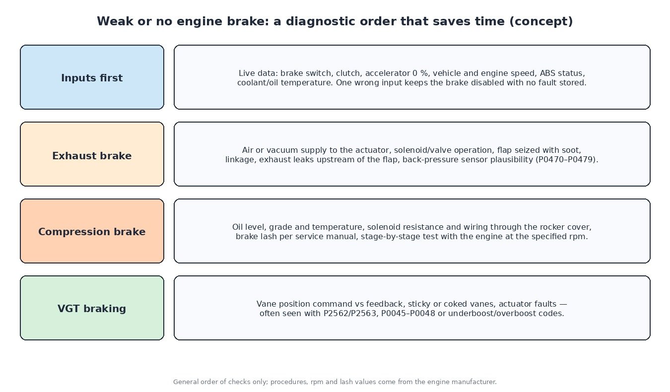
A weak or absent engine brake without a stored code is very often an enable-condition problem, so look at live data first: brake switch, clutch switch, accelerator position, vehicle speed, ABS status and temperatures. For exhaust brakes, check the air or vacuum supply, solenoid operation and whether the flap is seized with soot. For compression brakes, check oil level and grade, solenoid wiring through the rocker cover and the brake lash specified by the engine maker, then test stage by stage. With VGT braking, compare vane command with position feedback.
What it means for ECU calibration
Engine-brake enable logic, stages and protection limits live in the engine calibration, often next to boost and torque limits. A professionally engineered file changes fuelling and torque limits while keeping braking logic, exhaust pressure protection and ABS interaction as the manufacturer intended. On ECUFileMarket, engineered ECU and TCU files are delivered through the site upload flow. Checksum correction, when needed, is a separate paid option and is not included in file prices.
Related fault codes (DTCs)
Generic OBD-II codes (SAE J2012) commonly seen around exhaust brakes, back-pressure sensing and VGT braking. Heavy-duty vehicles may report the same faults as J1939 SPN/FMI codes; manufacturer wording varies.
| Code | Meaning | Typical causes |
|---|---|---|
| P0470 | Exhaust Pressure Sensor “A” Circuit | Open or short in the exhaust back-pressure sensor circuit, failed sensor, damaged connector near the exhaust |
| P0471 | Exhaust Pressure Sensor “A” Circuit Range/Performance | Blocked or cracked sensing tube, sensor reading implausible vs operating state, flap not moving as commanded |
| P0472 | Exhaust Pressure Sensor “A” Circuit Low | Signal shorted to ground, open reference supply, failed sensor |
| P0473 | Exhaust Pressure Sensor “A” Circuit High | Signal shorted to voltage, open ground, failed sensor, or a genuinely restricted exhaust |
| P0474 | Exhaust Pressure Sensor “A” Circuit Intermittent/Erratic | Loose pin, heat-damaged harness, condensation or soot in the sensing line |
| P0475 | Exhaust Pressure Control Valve “A” | Exhaust brake valve/solenoid circuit fault, failed actuator, wiring or connector damage |
| P0476 | Exhaust Pressure Control Valve “A” Range/Performance | Flap sticking from soot or corrosion, weak air/vacuum supply, linkage binding, actuator not reaching position |
| P0477 | Exhaust Pressure Control Valve “A” Low | Control circuit shorted low or open, failed solenoid coil |
| P0478 | Exhaust Pressure Control Valve “A” High | Control circuit shorted to voltage, driver or coil fault |
| P0479 | Exhaust Pressure Control Valve “A” Intermittent | Intermittent wiring, connector corrosion, actuator sticking only when hot or cold |
| P0045 | Turbocharger/Supercharger Boost Control “A” Circuit/Open | Open circuit to the VGT/boost control actuator or solenoid, failed actuator |
| P0046 | Turbocharger/Supercharger Boost Control “A” Circuit Range/Performance | Actuator not following command, sticking vanes, weak vacuum supply on pneumatic VGTs |
| P0047 | Turbocharger/Supercharger Boost Control “A” Circuit Low | Control circuit shorted low, damaged wiring |
| P0048 | Turbocharger/Supercharger Boost Control “A” Circuit High | Control circuit shorted to voltage, actuator or driver fault |
| P2562 | Turbocharger Boost Control Position Sensor “A” Circuit | Fault in the VGT position feedback circuit, failed position sensor in the actuator |
| P2563 | Turbocharger Boost Control Position Sensor “A” Circuit Range/Performance | Coked or sticking vanes, worn linkage, actuator position not matching command or learned range |
| P0234 | Turbocharger/Supercharger “A” Overboost Condition | VGT vanes stuck closed, actuator fault, boost control fault, sometimes a skewed boost sensor |
| P0299 | Turbocharger/Supercharger “A” Underboost Condition | Charge-air leaks, vanes stuck open, actuator faults, exhaust leaks before the turbine |
| P0500 | Vehicle Speed Sensor “A” | Missing or implausible road speed signal, which many strategies need to enable engine braking or downhill speed control |
| P0571 | Brake Switch “A” Circuit | Faulty or misadjusted brake pedal switch, wiring fault; can disable cruise and brake-related functions |
Closing
Exhaust brakes, compression-release brakes and VGT braking all turn the engine into a controlled resistance, and the ECU decides when they can work. Check the inputs, the air or oil supply and the actuators before blaming the engine.
Need an engineered ECU or TCU file for a truck, tractor, van, car or bike? Upload your original read at ECUFileMarket.