
A hybrid vehicle has two sources of drive torque, an engine and one or more electric motors, and a small group of control units must decide every few milliseconds how much each one delivers. The engine ECU is no longer the top of the chain. It receives torque requests from a hybrid control unit that also looks at battery state of charge, motor temperatures and brake demand. Here is how the layouts, high-voltage parts and control units fit together.
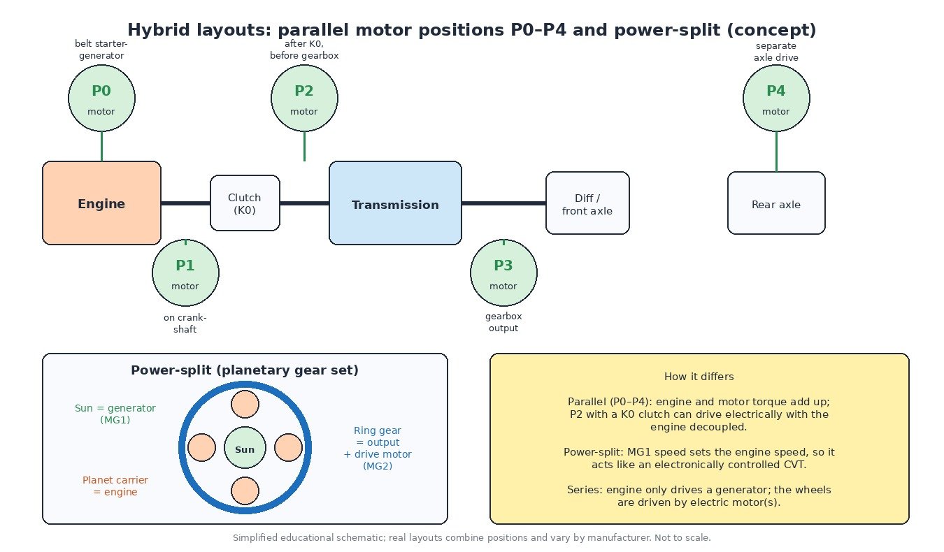
Hybrid layouts at a glance
Parallel hybrids are described by where the electric machine sits, positions P0 to P4:
- P0: a belt-driven starter-generator on the front of the engine. Common in 48 V mild hybrids.
- P1: the motor sits directly on the crankshaft, so it always turns with the engine.
- P2: the motor sits between the engine and the transmission, with a separating clutch (often called K0) on the engine side. Opening K0 allows pure electric driving through the normal gearbox.
- P3: the motor drives the transmission output.
- P4: the motor drives a separate axle, typically the rear, giving electric all-wheel drive.
A power-split hybrid works differently. A planetary gear set links the engine (on the planet carrier), a generator (MG1, on the sun gear) and the output with the drive motor (MG2, on the ring gear). By controlling MG1 speed, the system sets engine speed independently of road speed, so the unit behaves like an electronically controlled CVT. In a series hybrid the engine only drives a generator and the wheels are driven electrically.
The high-voltage system
Full and plug-in hybrids use a high-voltage (HV) battery built from many cells in series. Under UN ECE R100, anything above 60 V DC or 30 V AC is voltage class B and needs special protection, which is why HV cables are orange.
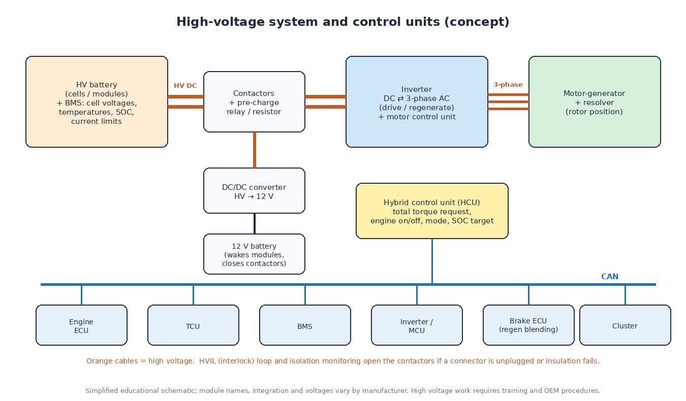
- Battery management system (BMS): monitors cell or module voltages, temperatures and current, estimates state of charge (SOC) and state of health, and tells the rest of the vehicle how much charge and discharge power is allowed right now.
- Contactors and pre-charge: relays that connect the battery to the HV bus. A pre-charge circuit charges the inverter capacitors gently before the main contactor closes.
- Inverter: converts DC to three-phase AC to drive the motor and turns AC back into DC during regeneration.
- Motor-generator: usually a permanent-magnet synchronous machine with a resolver that reports exact rotor position to the inverter.
- DC/DC converter: replaces the alternator on many hybrids, charging the 12 V battery from the HV bus.
Safety functions run constantly. The high-voltage interlock loop (HVIL) is a low-voltage circuit through HV connectors and covers; if it opens, the contactors open. An isolation monitor checks resistance between the HV system and the chassis and sets a fault if insulation drops.
How the control units coordinate
The hybrid control unit (HCU, sometimes integrated into the engine ECU or another module) is the torque coordinator. It turns pedal position, cruise requests and stability control interventions into one total wheel torque, then splits it between engine and motor based on SOC, battery power limits, temperatures and efficiency. It decides when the engine starts or stops, when to charge the battery with the engine and how much braking comes from regeneration. The brake ECU blends regenerative and friction braking so the pedal feels consistent.
All of this travels over CAN. The engine ECU still controls air, fuel and ignition, but it delivers the torque it is asked for, and it may be started at a chosen speed and load by the electric machine.
Cars, trucks, tractors and motorbikes
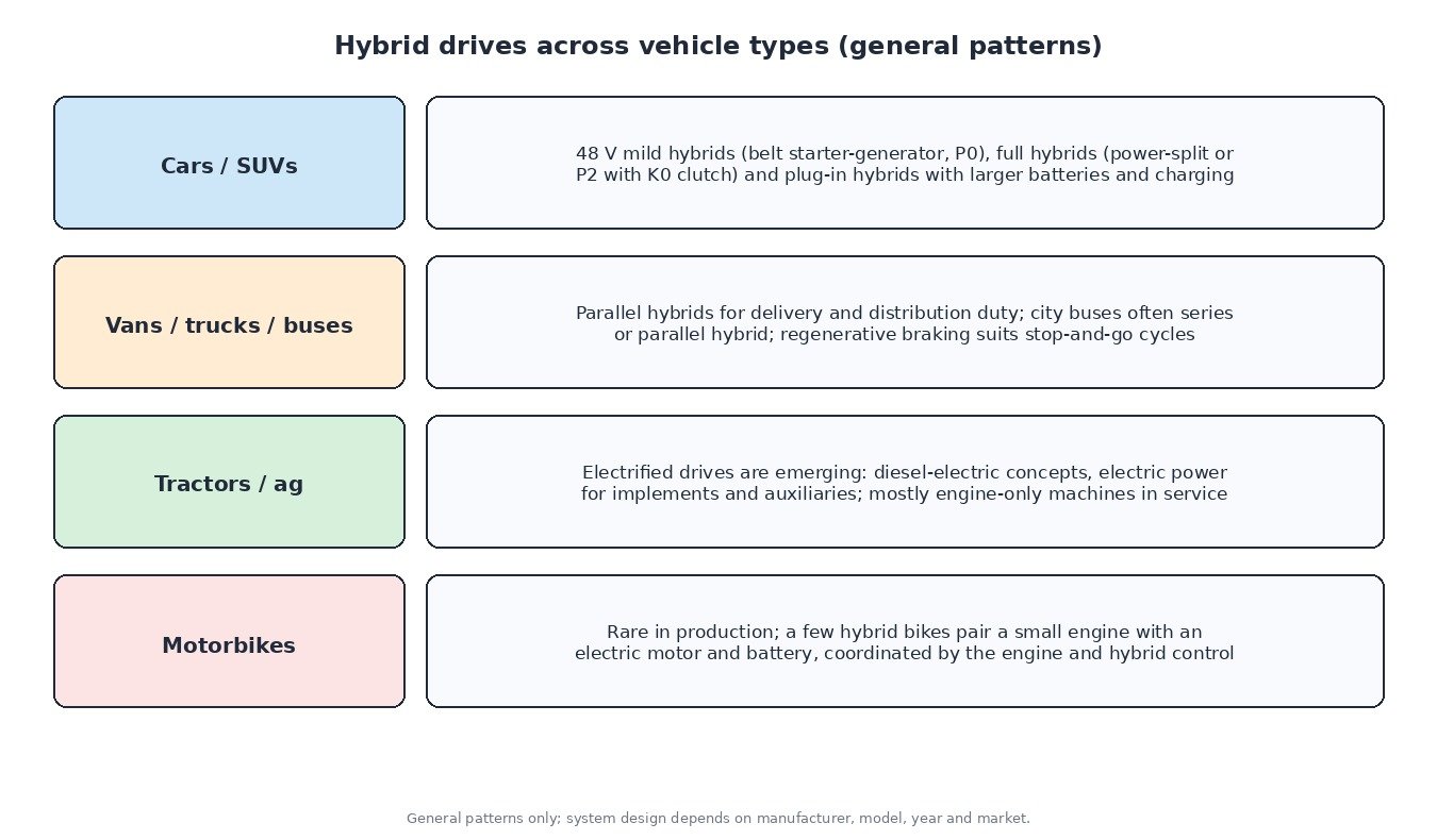
In cars, 48 V mild hybrids, full hybrids and plug-in hybrids are all common. Delivery trucks and city buses use parallel or series hybrids because stop-and-go driving gives plenty of braking energy to recover. In agriculture, electrified drives and electric power for implements are emerging, but most machines in service are still engine-only. Hybrid motorcycles are rare.
Diagnostics and safety
- Check the 12 V battery first. It wakes the control units and powers the contactors. A weak 12 V battery can stop a hybrid reaching READY even with a charged HV battery.
- Read every module. Engine, HCU, BMS, inverter and brake ECU each store their own codes, and one root cause often sets codes in several.
- Look at live data: module voltages and their spread, battery temperatures, SOC, inverter temperatures and coolant pump status.
- HV work is for trained technicians only. Follow the manufacturer’s de-energising procedure, remove the service disconnect, wait the specified time, use rated insulated gloves and verify absence of voltage before touching orange components.
What it means for ECU calibration
On a hybrid, engine torque is only one part of the system. The HCU, TCU and inverter have their own torque, speed and temperature limits, and the engine software is often matched to them. Changing engine torque without understanding that coordination can cause limp mode, plausibility faults or drivability problems. Hybrid calibration work needs the full original read and careful logging of engine and hybrid data. Emissions and safety functions stay in place.
Related fault codes (DTCs)
Generic OBD-II hybrid codes (SAE J2012). Exact wording differs by manufacturer, and many brands add their own codes for battery blocks and HV components, so always read every module.
| Code | Meaning | Typical causes |
|---|---|---|
| P0A0D | High Voltage System Interlock Circuit High | HVIL loop open: service plug or HV connector not fully seated, damaged interlock wiring or pins |
| P0A0F | Engine Failed to Start | Engine fault seen by the hybrid system: fuel supply, ignition, compression or engine sensor problems, empty tank |
| P0A1D | Hybrid Powertrain Control Module | Internal fault of the hybrid control unit, supply or ground problems, software issue |
| P0A1F | Battery Energy Control Module | BMS / battery control module fault, its power or ground, internal communication fault |
| P0A78 | Drive Motor “A” Inverter Performance | Inverter fault, inverter overheating, motor or HV cable insulation problem; check cooling first |
| P0A7E | Hybrid Battery Pack Over Temperature | Blocked battery cooling air intake or filter, failed cooling fan or pump, faulty temperature sensor |
| P0A7F | Hybrid Battery Pack Deterioration | Ageing cells or modules with high internal resistance, module imbalance, poor bus-bar connections |
| P0A80 | Replace Hybrid Battery Pack | Voltage difference between blocks/modules too large; often stored with manufacturer block-voltage codes |
| P0A93 | Inverter “A” Cooling System Performance | Low coolant in the inverter circuit, failed electric coolant pump, air in the circuit, blocked radiator or hoses |
| P0A94 | DC/DC Converter Performance | Boost or DC/DC converter fault, overheating from poor inverter cooling, internal failure of the converter assembly |
| P0AA6 | Hybrid Battery Voltage System Isolation Fault | Insulation breakdown between HV system and chassis: damaged orange cable, coolant or moisture in HV parts, electric A/C compressor, battery leakage |
Closing
A hybrid is a coordinated system: understand the layout, respect the high voltage and read every control unit before drawing conclusions.
Need an engineered ECU or TCU file for a car, van, truck, tractor or bike? Upload your original read at ECUFileMarket.