
On most turbocharged petrol engines, and on many diesels and off-road machines, the turbocharger has fixed geometry. How much boost it makes is decided by a small valve on the exhaust side: the wastegate. Controlling that valve precisely across every rpm, load, temperature and altitude is one of the ECU’s most important jobs. This guide explains how wastegate boost control works, how the ECU closes the loop, how to diagnose boost faults, and what it means for engineered tuning files.
What the wastegate does
A turbine sized for quick low-rpm response would keep accelerating as engine speed rises and soon overboost the engine. The wastegate is a bypass: when it opens, part of the exhaust flows around the turbine, so turbine speed and boost stop rising. When it is closed, all exhaust drives the turbine for the fastest spool. Variable geometry turbos (VGT), covered in our earlier guide, use adjustable vanes instead; this article is about wastegated turbos.
Internal vs external wastegates
- Internal: a flap built into the turbine housing, moved by an actuator rod. Compact and used on almost every production car.
- External: a separate valve on the exhaust manifold with its own spring and diaphragm. It handles more flow and gives finer control at high power, so it is common in motorsport and big turbo builds.
Pneumatic actuators and the boost control solenoid
The classic actuator is a diaphragm can whose spring holds the wastegate closed. On petrol engines boost pressure is fed to the diaphragm, and once it overcomes the spring the wastegate opens. The spring therefore sets base boost.
To run above base boost, the ECU uses a boost control solenoid, often called a frequency valve (the N75-style valve on many VAG engines is a familiar example). It is driven with a fixed-frequency PWM signal, and the ECU varies the duty cycle to bleed off part of the pressure reaching the actuator. On many layouts more duty means more boost, but the direction depends on the plumbing. Diesel wastegates are often vacuum-operated, with an electro-pneumatic pressure converter doing the same job.
Electronic wastegate actuators
Many newer petrol engines use an electric actuator: a DC motor, gearing and an integrated position sensor. The ECU commands a wastegate position and reads it back, independent of available boost or vacuum. That allows strategies such as an open wastegate at light load to cut exhaust backpressure. Replacement actuators usually need an adaptation so the ECU learns the end stops.
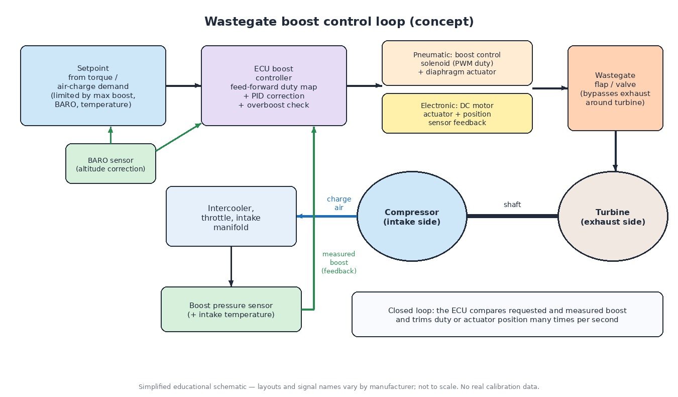
How the ECU closes the loop
- Setpoint: requested boost comes from the torque or air-charge demand: the air mass the cylinders need and the manifold pressure that delivers it.
- Limits: the setpoint is capped by a maximum boost map, intake temperature corrections and a pressure ratio or turbo speed limit. Using the BARO sensor, the ECU lowers the absolute target at altitude so the compressor does not overspeed.
- Feed-forward (pilot) control: a duty or position map gives the base command for the current rpm and target, so response is quick.
- PID-style correction: proportional and integral (sometimes derivative) terms trim the command using the error between requested boost and the boost pressure sensor. Integral limits prevent wind-up.
- Overboost protection: if actual boost exceeds target by a set margin for a set time, the ECU opens the wastegate, cuts torque and stores P0234.
Boost leaks and diagnostics
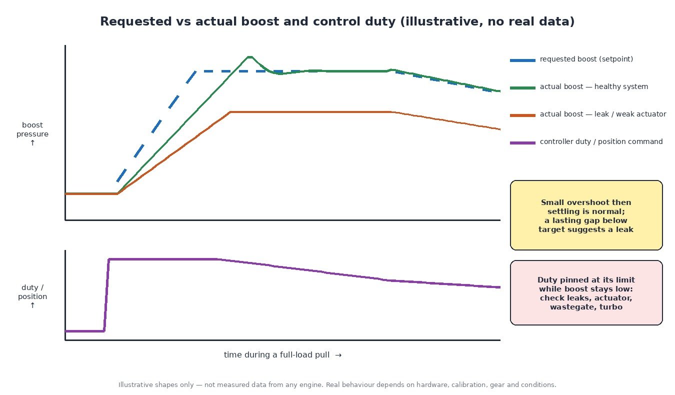
Start with a data log of requested vs actual boost plus solenoid duty or actuator position during a full-load pull in a mid gear. A healthy system tracks the target with a small overshoot. If boost stays low while the command sits at its limit, check:
- charge pipes, couplers, intercooler and throttle seal; a smoke test of the intake tract finds leaks fastest,
- split, swapped or collapsed actuator hoses,
- a sticking or worn wastegate flap and linkage,
- a torn bypass (recirculation) valve diaphragm,
- exhaust leaks before the turbine, then the turbo itself.
At key-on, engine off, the boost sensor and BARO should both read ambient pressure.
Cars, trucks, tractors and recreational vehicles
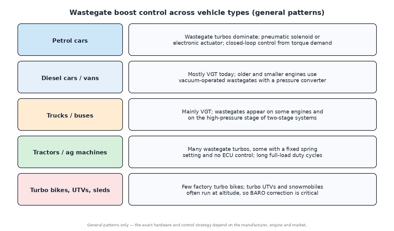
Petrol cars almost all use wastegate turbos. Diesel cars and vans are now mostly VGT, though older and smaller engines use vacuum wastegates. Trucks and buses mainly use VGT, with wastegates on some engines and on the high-pressure stage of two-stage systems. Tractors often use wastegate turbos, some with a fixed spring setting and no ECU control, and long full-load work puts thermal limits first. Factory turbo motorbikes are rare, but turbo side-by-sides and snowmobiles often run at high altitude, so BARO correction and turbo speed limits matter even more.
Related fault codes (DTCs)
Generic OBD-II codes per SAE J2012. Exact wording and code usage vary between manufacturers.
| Code | Meaning | Typical causes |
|---|---|---|
| P0234 | Turbocharger/Supercharger “A” Overboost Condition | Wastegate stuck closed, faulty boost control solenoid, split or misrouted actuator hose, target beyond hardware capability |
| P0299 | Turbocharger/Supercharger “A” Underboost Condition | Boost leaks, wastegate stuck open, weak actuator diaphragm, worn turbo, exhaust leak before the turbine |
| P0236 | Turbocharger/Supercharger Boost Sensor “A” Circuit Range/Performance | Reading implausible against BARO or the air model, contaminated sensor, leaking sensor seal |
| P0237 | Turbocharger/Supercharger Boost Sensor “A” Circuit Low | Open or grounded signal wire, missing 5 V reference, faulty sensor |
| P0238 | Turbocharger/Supercharger Boost Sensor “A” Circuit High | Signal shorted to voltage, open ground, faulty sensor |
| P0243 | Turbocharger/Supercharger Wastegate Solenoid “A” | Open or shorted solenoid coil, wiring or connector fault |
| P0244 | Turbocharger/Supercharger Wastegate Solenoid “A” Range/Performance | Sticking or internally leaking solenoid, blocked ports or filter |
| P0245 | Turbocharger/Supercharger Wastegate Solenoid “A” Low | Control circuit shorted to ground |
| P0246 | Turbocharger/Supercharger Wastegate Solenoid “A” High | Control circuit shorted to voltage or open, faulty solenoid |
| P0045 | Turbocharger/Supercharger Boost Control “A” Circuit/Open | Open circuit to the boost control solenoid or actuator, corroded connector |
| P2562 | Turbocharger Boost Control Position Sensor “A” Circuit | Actuator position sensor or wiring fault |
| P2563 | Turbocharger Boost Control Position Sensor “A” Circuit Range/Performance | Implausible position, sticking linkage, actuator not adapted after replacement |
| P0033 | Turbocharger/Supercharger Bypass Valve “A” Control Circuit | Open circuit to the electric bypass (recirculation) valve |
| P0034 | Turbocharger/Supercharger Bypass Valve “A” Control Circuit Low | Control circuit shorted to ground |
| P0035 | Turbocharger/Supercharger Bypass Valve “A” Control Circuit High | Control circuit shorted to voltage, faulty valve |
| P2261 | Turbocharger/Supercharger Bypass Valve “A” – Mechanical | Torn diaphragm or valve stuck open, venting boost to the compressor inlet |
| P2227 | Barometric Pressure Sensor “A” Circuit Range/Performance | Implausible ambient pressure reading, often a sensor inside the ECU; upsets altitude correction |
What it means for tuning
Raising boost is never one number. An engineered calibration adjusts boost target maps together with maximum boost and pressure-ratio limits, pilot duty or position maps and, where needed, controller gains, so the engine reaches the new target without overshoot or oscillation. Overboost protection must stay effective, the target must remain inside the compressor’s efficient range and speed limit, and altitude and temperature corrections should never be disabled. Fuelling, ignition and the torque model must then match the new air charge. Checksum correction, where required, is available on ECUFileMarket as a separate paid option.
Ready for an engineered tuning file with properly matched boost control? Upload your original ECU read at ECUFileMarket.