
Open almost any modern ECU file and you will not find a simple “fuel map” that decides how hard the engine pulls. Since the late 1990s most petrol and diesel engine controllers have been built around a torque-based structure: every function that wants something from the engine asks for it in newton-metres, and the ECU then decides how to deliver it. Understanding that structure is the difference between a calibration that works smoothly with the gearbox, traction control and cruise control, and one that only looks good on paper. This guide explains how torque models work, where limiters sit, and what it means for diagnostics and tuning.
Why ECUs switched to torque
Older engine controllers translated pedal position more or less directly into throttle angle or injected quantity. That became a problem as more systems needed to influence the engine: automatic gearboxes wanted torque cut during shifts, stability control wanted to reduce power on a slippery road, and idle control had to cover the load of the air-conditioning compressor. Torque is the common language all of these systems can use. Bosch ME7 on petrol engines is a well-known early example, and today the same idea runs through petrol, diesel, truck, tractor and motorcycle ECUs.
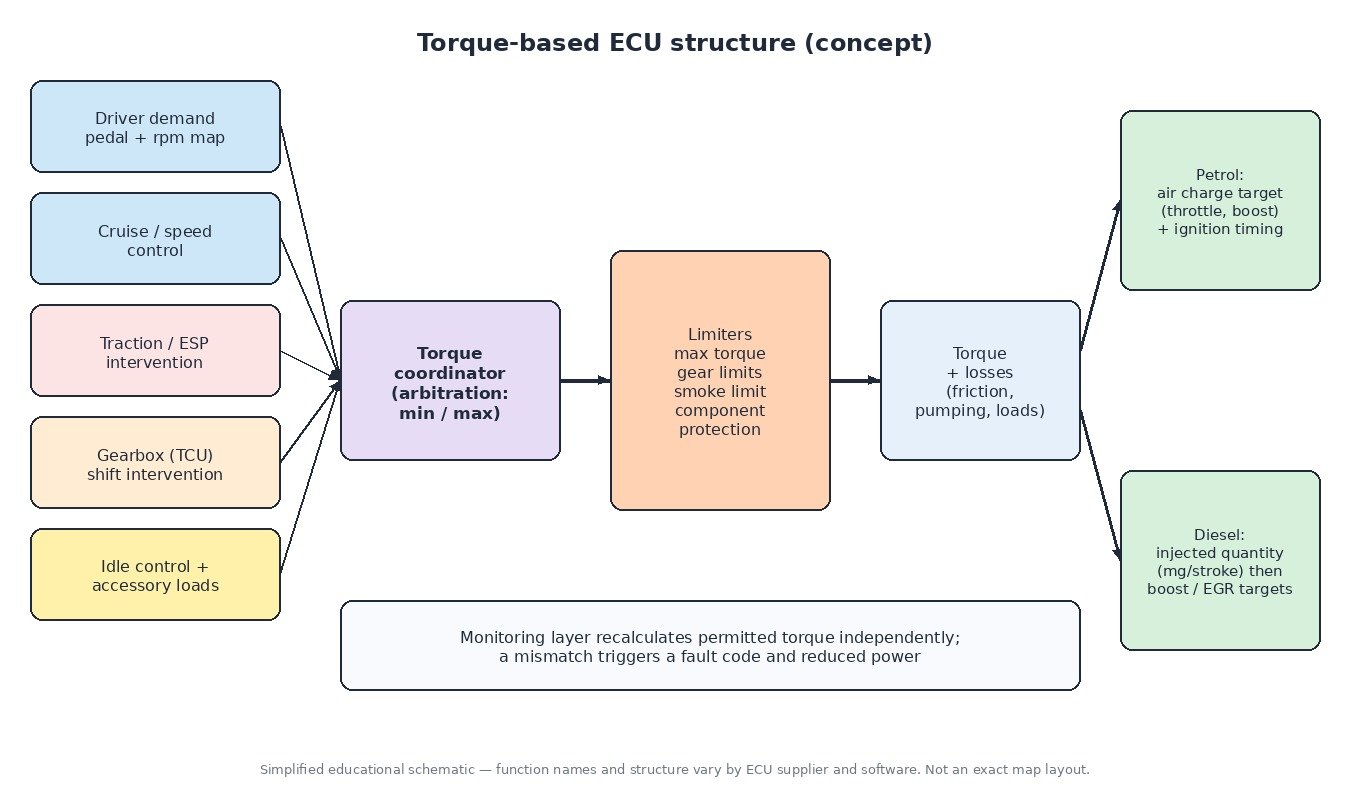
Step 1: collecting torque requests
The first input is driver demand. The accelerator pedal position and engine speed are looked up in a pedal map, which outputs a requested torque (absolute or as a percentage of the maximum). Other requests run alongside it:
- Cruise control or speed limiter asks for the torque needed to hold or cap road speed.
- Traction and stability control ask for less torque when wheels spin.
- The gearbox control unit (TCU) asks for a short torque reduction during shifts, and may cap torque in certain gears.
- Idle speed control asks for extra torque to hold idle when loads such as the alternator or A/C compressor switch in.
Step 2: the torque coordinator
A coordinator arbitrates between all requests. Reductions (traction control, gearbox interventions) normally win through a minimum selection, while requests that must be honoured, such as idle stability, use a maximum selection. The result is a single target torque that represents what the engine should deliver at the crankshaft or clutch.
Step 3: limiters
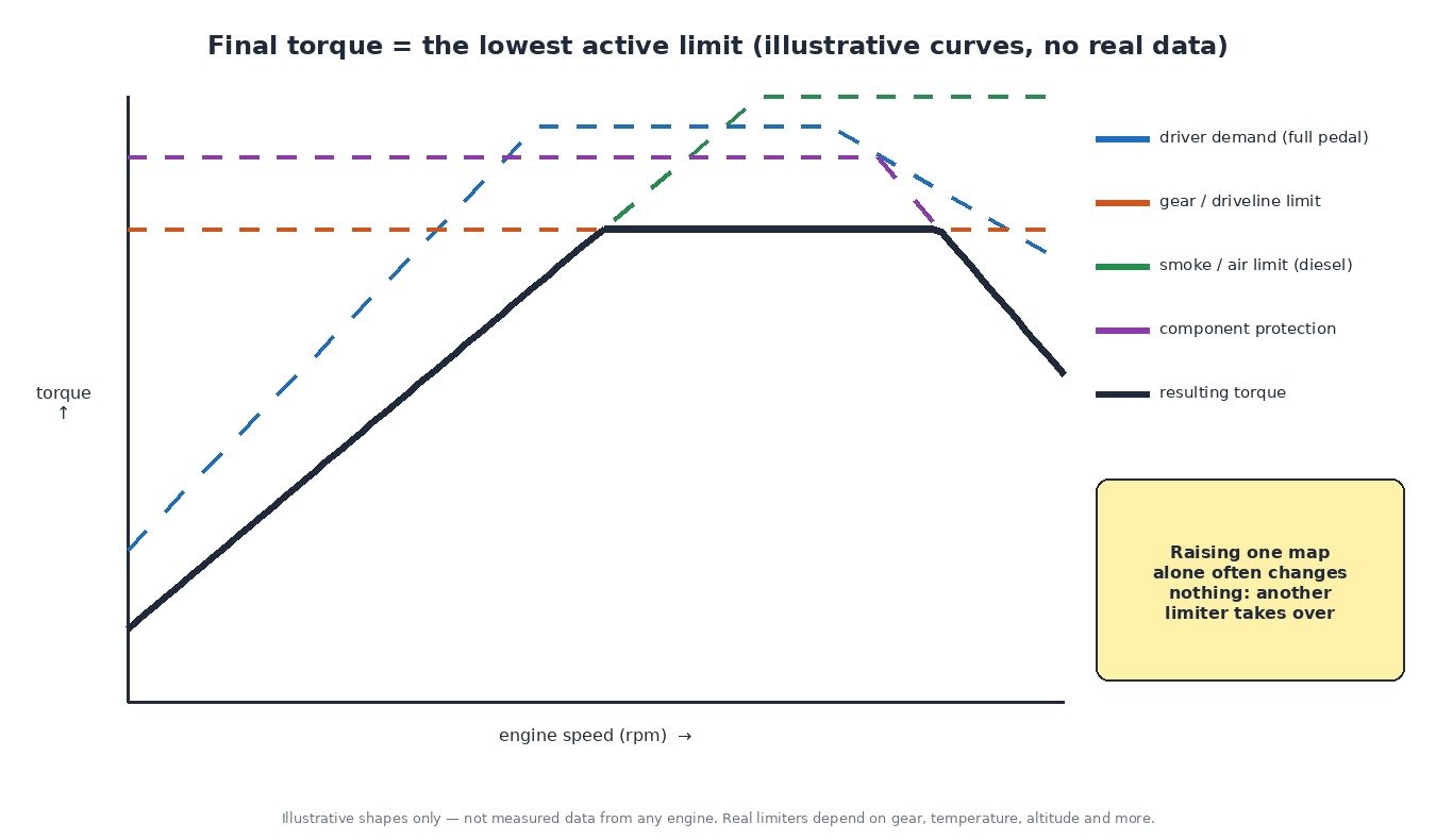
Before the target reaches the actuators, it passes through a chain of limiters. The lowest active limit wins.
- Maximum engine torque over engine speed, the overall ceiling for the calibration.
- Gear and driveline limits that protect the gearbox, clutch and driveshafts, often different for each gear.
- Smoke or air limits on diesels, which restrict injected fuel to what the available air mass can burn cleanly.
- Component protection based on exhaust gas temperature, coolant and intake temperature, turbo speed and altitude.
- Engine speed and road speed limiters.
Step 4: converting torque into actuator commands
The ECU adds the engine’s own losses to the target: internal friction, pumping losses and accessory loads. The result is the indicated torque the combustion has to produce. How that is delivered depends on the engine type.
Petrol engines
On a petrol engine torque is mostly a function of air charge. The ECU converts the torque target into a required cylinder air mass using its efficiency model, then sets throttle angle, and on turbo engines a boost target, to achieve it. Ignition timing is the fast path: the ECU can retard the spark for an immediate torque reduction during a gearshift or traction event, faster than the air path can respond.
Diesel engines
On a diesel, torque is mainly controlled by fuel. A torque-to-quantity conversion turns the target into an injected quantity in milligrams per stroke. The air system (boost pressure and EGR) then follows that quantity, and the smoke limiter makes sure fuel never exceeds what the measured air can support.
Torque monitoring and safety
Because the ECU controls engine output electronically, it also checks itself. A separate monitoring layer, often on a different software level, recalculates the permitted torque from pedal position and engine speed and compares it with what the main calculation is delivering. A processor watchdog checks that the monitoring itself is running. If the values disagree beyond a tolerance, the ECU stores a fault such as P061B and enters a reduced-power or limp-home mode.
Cars, trucks, tractors and bikes
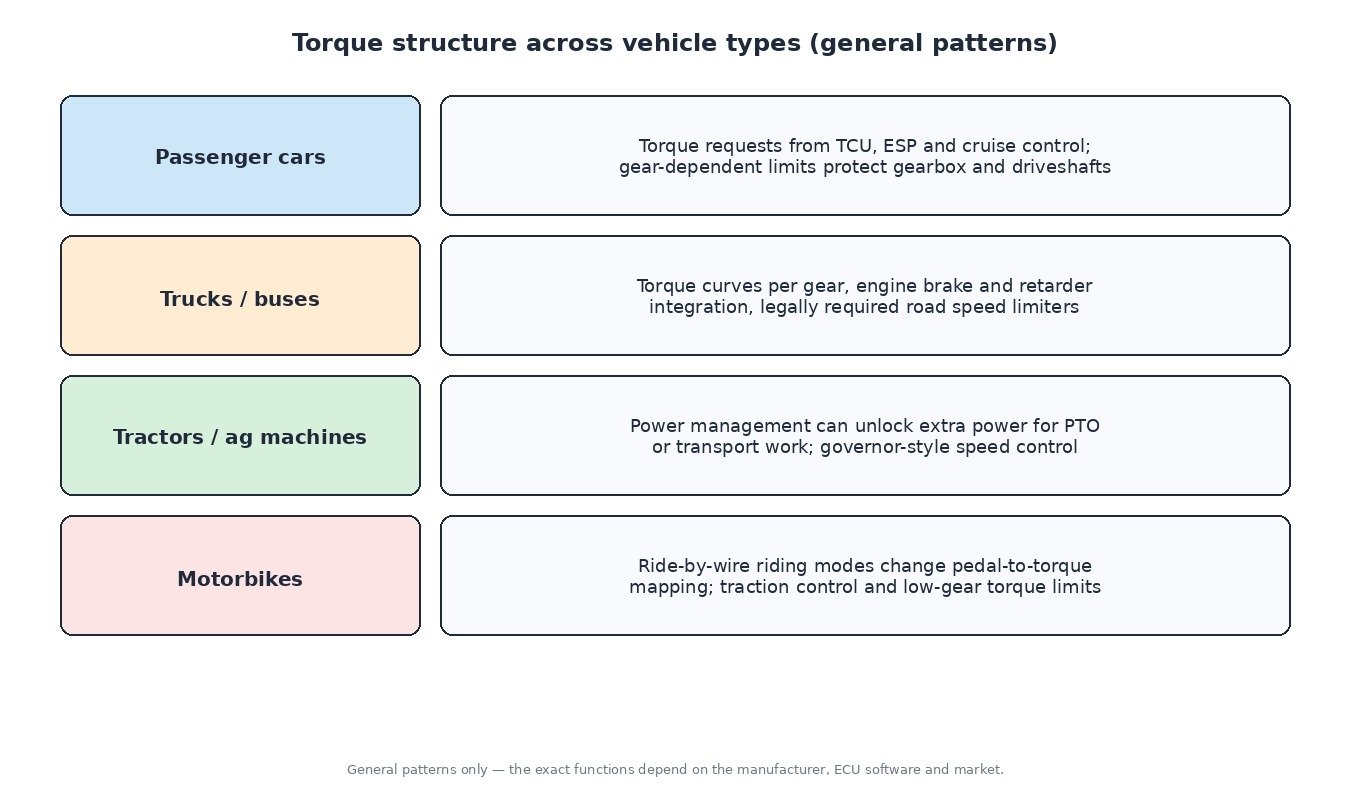
The structure is similar across vehicle types, but the priorities differ. Passenger cars lean heavily on gearbox and stability interventions. Trucks and buses add torque curves per gear, engine brake integration and legally required road speed limiters. Many modern tractors use power management that can unlock extra power for specific tasks such as PTO work or transport. On motorbikes, ride-by-wire riding modes change the pedal-to-torque mapping, and traction control and low-gear torque limits shape delivery.
Diagnostics tips
- Lack of power with no obvious fault often means a limiter is active. Live data such as requested versus actual torque, limiting reason or boost target versus actual helps identify which one.
- Always check the gearbox module too. A TCU fault can cap engine torque even when the engine ECU looks clean.
- A brake switch correlation fault can disable cruise control and trigger brake-override torque reduction.
- Torque plausibility codes after a software change point to an inconsistent calibration, not necessarily a hardware failure.
Related fault codes (DTCs)
Generic OBD-II codes per SAE J2012. Exact wording varies slightly between manufacturers.
| Code | Meaning | Typical causes |
|---|---|---|
| P061A | Internal Control Module Torque Performance | Delivered torque does not match the permitted torque in the monitoring layer, inconsistent calibration, internal ECU fault |
| P061B | Internal Control Module Torque Calculation Performance | Mismatch between the main torque calculation and the monitoring calculation, often after an inconsistent modification, sometimes an internal fault |
| P061C | Internal Control Module Engine RPM Performance | Engine speed calculation plausibility error between processor levels, crank signal disturbance, internal fault |
| P061D | Internal Control Module Engine Air Mass Performance | Air mass calculation plausibility error inside the ECU, inconsistent air model, internal fault |
| P0219 | Engine Overspeed Condition | Engine taken beyond the rev limit (often a missed downshift), runaway engine, speed signal fault |
| P0234 | Turbocharger/Supercharger “A” Overboost Condition | Sticking wastegate or VGT vanes, faulty boost control solenoid or actuator, boost target above hardware capability |
| P0299 | Turbocharger/Supercharger “A” Underboost Condition | Boost leaks, worn turbo, actuator or vacuum faults, boost target the hardware cannot reach |
| P0101 | Mass or Volume Air Flow “A” Circuit Range/Performance | Contaminated or failing MAF, intake leaks, air model no longer matching the hardware |
| P0068 | MAP/MAF – Throttle Position Correlation | Intake leaks, dirty throttle body, MAP or MAF sensor fault, air model mismatch |
| P2135 | Throttle/Pedal Position Sensor/Switch “A”/”B” Voltage Correlation | Worn throttle body or pedal sensor tracks, wiring or connector faults, shared reference voltage problem |
| P2138 | Throttle/Pedal Position Sensor/Switch “D”/”E” Voltage Correlation | Faulty accelerator pedal sensor, wiring or connector faults |
| P0504 | Brake Switch “A”/”B” Correlation | Misadjusted or faulty brake light switch, wiring fault; disables cruise control and brake-override torque functions |
| P0700 | Transmission Control System (MIL Request) | The TCU has stored its own fault; read the gearbox module for the actual code |
| U0101 | Lost Communication With TCM | Gearbox control unit offline, CAN wiring fault; torque interventions during shifts no longer possible |
What it means for tuning
In a torque-based ECU, raising one map on its own rarely does what you expect, because another limiter simply takes over. A professional calibration keeps the whole chain consistent: pedal maps, torque limiters, torque-to-quantity or air charge conversion, smoke limits and the torque value reported to the gearbox and stability control. If the reported torque is wrong, an automatic gearbox can shift harshly or let clutches slip, and the monitoring layer can trigger limp mode. Mechanical limits matter too, so gearbox and clutch capacity should always be part of the plan. Checksum correction is required after any change and is offered on ECUFileMarket as a separate paid service.
Ready for an engineered tuning file built around the full torque structure? Upload your original ECU read at ECUFileMarket.